Do you have a question about the King Industrial CT-381 and is the answer not in the manual?
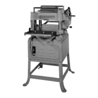
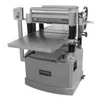
Main structural casting for the spindle assembly.
Assembly holding the cutting blades.
Roller feeding material into the planer.
Safety feature to prevent kickback.
The primary surface for planing operations.
Rollers supporting the planing table.
Collects dust generated during operation.
The main structural base of the column assembly.
The main vertical support structure.
Screw responsible for vertical table adjustment.
The primary stand supporting the machine cabinet.
The 3 horsepower motor powering the planer.
Electrical switch controlling motor operation.
Housing for the gear mechanisms.
Pulley that drives the cutterhead.
Component that breaks up wood chips.
The legs providing stability to the stand.
Plates that reinforce the stand structure.
Plate for mounting various machine parts.
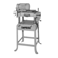
Main structural casting for the spindle.
Assembly for the cutting knives.
Roller for feeding material into the machine.
Safety feature to prevent kickback.
The main planing surface.
Component for dust collection.
Bracket supporting the feed rollers.
Housing for the worm gear mechanism.
Main structural base of the column assembly.
Vertical support structure.
Screw for table elevation adjustment.
Main stand for the machine.
The primary power unit.
Electrical control for the motor.
Cable for supplying electrical power.
Housing for the gear train.
Pulley driving the cutterhead.
Component for managing wood chips.
Bearing supporting rotating shafts.
Support legs for the planer stand.
Reinforcing plates for the stand.
Plate for mounting components.
| Motor | 3 HP |
|---|---|
| Number of Knives | 3 |
| Frequency | 60 Hz |
| Maximum Cutting Width | 15" |
| Cutterhead Speed | 5000 RPM |
| No Load Speed | 5000 RPM |