Do you have a question about the King Industrial KC-530FXR and is the answer not in the manual?
Covers the limited warranty period and terms for the planer.
Requirement to retain dated proof of purchase for warranty claims and servicing.
Information on obtaining replacement parts from authorized King Canada service centers.
Explains what the limited warranty covers, exclusions, and limitations.
Guidance to find updated parts diagrams and lists on the King Canada website.
15 essential safety rules for safe operation of industrial machinery.
13 critical safety measures specific to the operation of the 20" Extreme Planer.
Lists key technical data including dimensions, motor, and performance metrics.
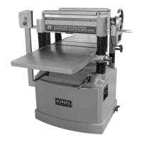
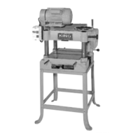
Identifies and describes the main external parts and controls of the planer.
Specifies the 220V, 40 AMP circuit breaker requirement and related warnings.
Details the importance and correct method for grounding the planer for safety.
Advises against extension cords, providing specs and warnings if used.
Explains the function of the magnetic switch, ON, and emergency STOP buttons.
Steps for inspecting, cleaning, and preparing the planer after delivery.
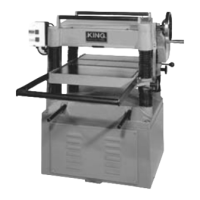
Instructions on using lifting handles and the mobile base for safe movement.
Guides on attaching the extension tables to the planer's main table.
Steps for installing the handwheel used for adjusting table height.
Instructions for assembling the standard dust collector hood to the planer.
Procedure for verifying and maintaining the correct gear box oil level.
Explains how to adjust table height for the desired cutting depth.
Details on adjusting the two available feed speeds using the lever.
Essential steps for operating the planer safely and effectively.
Outlines recommended maintenance tasks at different intervals.
Specific lubrication points, intervals, and suitable lubricant types.
Step-by-step guide for changing the gear box oil.
Instructions for V-belt maintenance, tensioning, and replacement.
Procedure for rotating or replacing carbide cutter inserts for sharp edges.
How to ensure proper alignment of motor and cutterhead pulleys to prevent belt wear.
Guidance on setting table roller height based on wood type and finish.
Procedure for adjusting components using wood blocks and feeler gauge.
Detailed steps for adjusting roller, chipbreaker, and pressure bar heights.
How to adjust the elevation drive chain tension to remove slack over time.
Setting infeed/outfeed roller spring tension for uniform feed pressure.
How to set the chip deflector position for optimal chip removal.
Instructions for cleaning and maintaining anti-kickback safety features.
Identifies common issues, probable causes, and solutions for planer operation.
This document outlines the operation, maintenance, and safety procedures for a 20-inch, 5HP extreme planer equipped with a spiral cutterhead. The planer is designed for industrial use and comes with a 2-year limited warranty, emphasizing the importance of proper maintenance and adherence to safety guidelines to ensure its longevity and safe operation.
The planer's primary function is to precisely reduce the thickness of wood workpieces and achieve a smooth, consistent finish. It is equipped with a powerful 5HP motor and a spiral cutterhead, which utilizes multiple small carbide inserts to achieve efficient and high-quality cuts. The machine features a robust construction, including a built-in mobile base for easy positioning and extension tables to support longer workpieces. The depth of cut is adjustable via a handwheel, allowing for precise control over the material removal. Two feed speeds are available, enabling users to select the optimal rate for dimensioning or finishing passes. An integrated dust collector hood helps maintain a clean work environment by efficiently capturing wood chips and dust.
The planer is designed for ease of use while prioritizing safety. Before operation, users are instructed to familiarize themselves with the manual, ensure all tools and foreign objects are removed from the machine, and wear appropriate safety gear, including safety glasses and a dust mask. The machine requires a 220V, 40 amp circuit breaker connection, and proper grounding is crucial to prevent electrical shock.
The operation sequence begins with adjusting the table height. The table height adjustment handwheel allows for precise control over the depth of cut, with each full turn adjusting the table by 1/16 inch. Locking knobs secure the table in place during operation. The planer offers two feed speeds, 16 ft./min. for dimensioning and 20 ft./min. for finishing passes, controlled by a speed shift lever. It is critical to change speeds only when the machine is running without a load to prevent damage to the gear box.
When feeding a workpiece, it is recommended to surface plane it on a jointer first to ensure it is perfectly flat, which prevents kickback and ensures a consistent cut. The first cut should be light, between 1/32" and 1/16". The operator should stand to the side of the planer to avoid injury from potential kickback. The machine's anti-kickback fingers are a crucial safety feature, designed to prevent the workpiece from being ejected back towards the operator. Users are advised to utilize the full width of the planer table by feeding workpieces at different positions (right, left, and center) to prolong the sharpness of the cutter inserts. The planer is intended for natural wood fibers and should not be used with wood composites like MDF or particle board, nor wood with high moisture content, as this can cause excessive wear to the cutter inserts and motor. In case of a jammed workpiece, the planer must be stopped, and the power cord disconnected before attempting to remove the obstruction.
Regular maintenance is essential for the planer's optimal performance and longevity, as outlined in a detailed cleaning and lubrication schedule.
The manual also includes a troubleshooting guide to address common issues such as the motor not starting, motor overheating, slow cutting, vibration, excessive snipe, long lines on the board, and a glossy finish, providing probable causes and solutions for each.
| Maximum Cutting Depth | 1/8 inch |
|---|---|
| Motor | 3 HP |
| Cutterhead Speed | 5, 000 RPM |
| Number of Knives | 3 |
| Motor Power | 3 HP |
| Voltage | 220V |
| Maximum Cutting Width | 13 inches |