Page 5 of 11 King Pigeon Hi-Tech. Co., Ltd. Ver 1.3
Remote Relay Switch
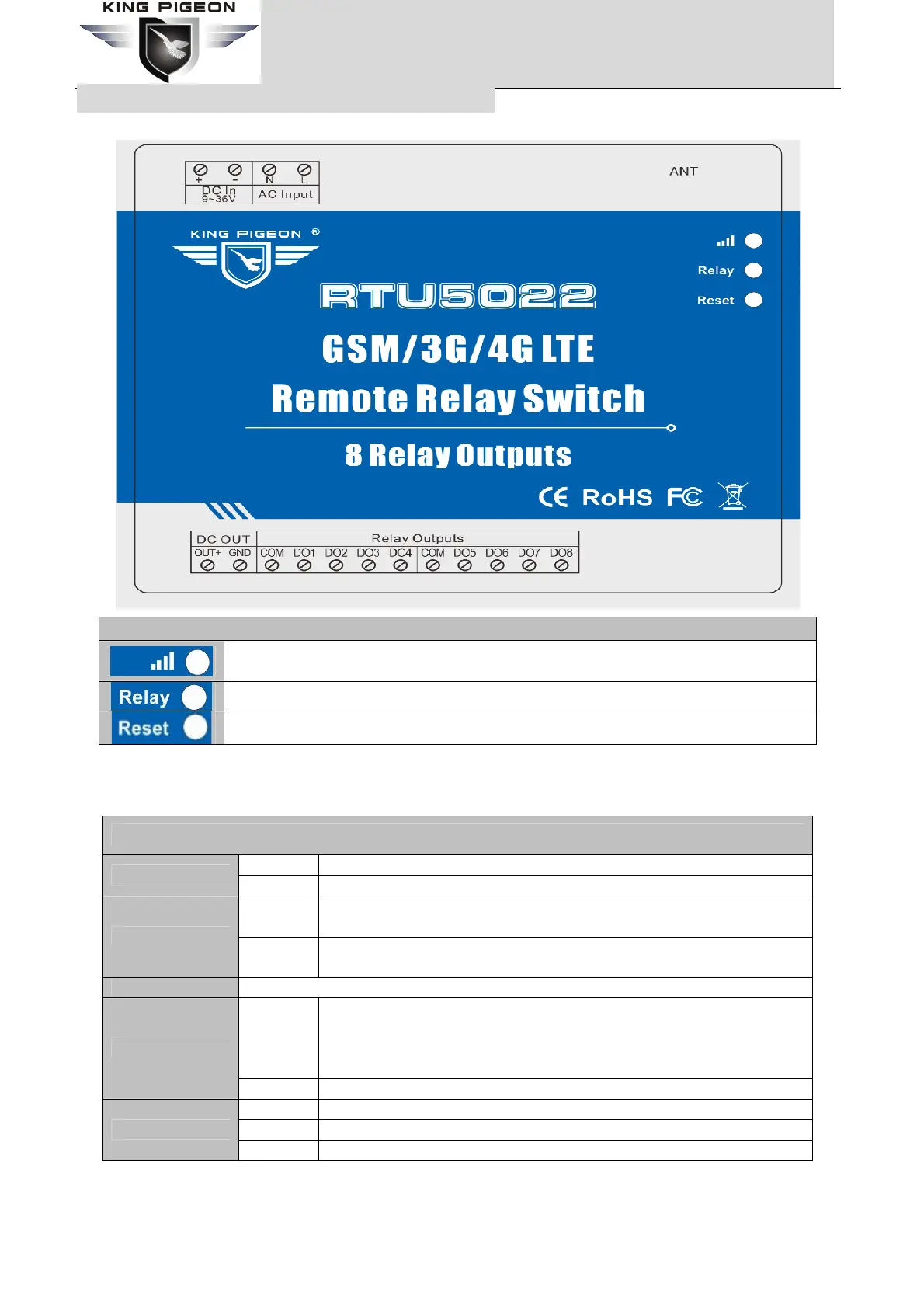
6. Physical Layout and Installation Diagram
1) LED Indicator Instruction
LED Indicator Instruction
Cellular indicator, registering cellular Network flicks quickly, registered successful will 1
seconds flick once.
Relay indicator, any one relay close, will turn on.
Reset indicator, will turn on 5seconds while reset operation successful.
2) Interface Instruction
See below interface, please contact the correct wires.
Interface Instruction
+ DC9~36V positive input, 1.5A, for power on the Unit;
DC In 9~36V
– DC9~36V negative input, 1.5A, for power on the Unit;
N
Neutral wire, connect to 110~220VAC @50Hz alternating current, for
power on the Unit;(Optional)
AC Input
L
Live wire, connect to 110~220VAC @50Hz alternating current, for
power on the Unit; (Optional)
ANT GSM/3G/4G antenna.
OUT+
DC voltage output positive, the output voltage = DC Input voltage. Only
when the device powered on by DC power, these ports will output DC
voltage. If the device powered on by AC power, these ports will not
output DC voltage.
DC OUT
GND DC voltage output negative input.
COM Relay negative input.
DO1 Relay 1 positive input.
Relay Outputs
DO2~8 Relay 2~8 positive input.
The unit provides 2/4/8 relay outputs; it can be used for control different device according to requirements.
The connection diagram is below:
 Loading...