OPERATING 5-21
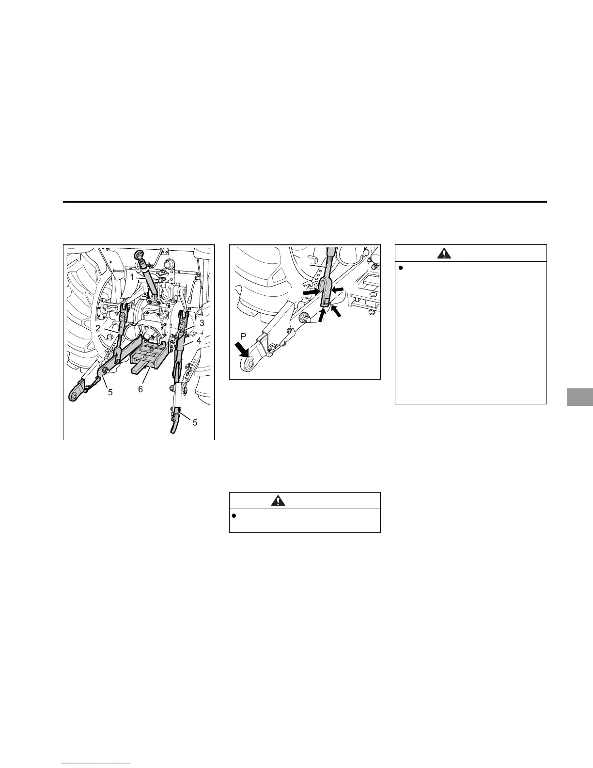
1
2
3
4
5
ADJUSTMENT OF THE LIFT ROD
ATTACHING DEVICES FOR AN IMPLE-
MENT (FOR GENERAL IMPLEMENT)
A12O526A
(1) Top Link
(2) Crank Lifting Rod (L)
(3) Stopper
(4) Crank Lifting Rod (R)
(5) Lower Link
(6) Swing Drawbar Frame
WARNING
Before disconnecting a lift rod
from the lower link, stop the en-
gine and lower attached equip-
ment to the ground. Ensure at-
tached equipment is correctly
supported and that no residual
pressure remains in the hydrau-
lic system before removing the lift
rod securing pin. Move the hy-
draulic lift control lever fully
backward and forward several
times, in order to remove any re-
sidual pressure, then move the le-
ver fully forward.
1. Adjust the position of the implement
evenly by moving the lifting rod.
2. After the adjustment is completed, se-
cure with the stopper.
3. Correct positioning of the lifting rod to
the lower link is shown below. Posi-
tioning varies dependent upon the type
of implement.
CAUTION
Never use lower link 2 (Back)
hole.
A12O527A
(1) Check Link (2) Pin
3 POINT HITCH