K110sm3e1.doc
3-2
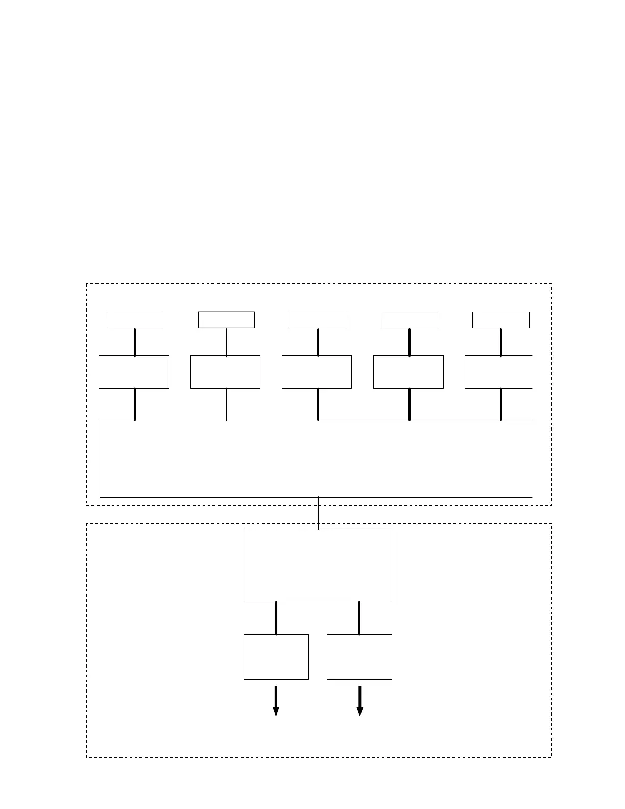
3. 1 Data flow in scan and copy
There are CIS Units, CIS Controller PCB and Data Controller PCB in the scanner unit, which take
image reading and processes the data.
1. The CIS Units read the image pattern of original and then send the analog data to the CIS
Controller Board.
2. The CIS Controller Boards converts the analog data into digital data and then send to the Data
Controller PCB.
3. The Data Controller PCB takes a proper image process according to the UI setting on a KIP
printer.
It outputs the image data to the IPS through the USB 2.0.
4. The IPS outputs the image data to the KIP printer through the Interface 8 on copy, or it outputs
to the Network PC through the LAN cable on Scan to File.
CIS
CIS CIS CIS CIS
CIS Controller PCB
(A/D Conversion)
Analog data
Digital data
CIS Controller PCB
(A/D Conversion)
CIS Controller PCB
(A/D Conversion)
CIS Controller PCB
(A/D Conversion)
CIS Controller PCB
(A/D Conversion)
Data Controller PCB
(Several image process)
USB 2.0
IPS Controller
Interface 8 LAN
Printer part Network PC
Printing out
of the Copy
Saving as an
image file
KIP 600 Digital Image Scanner
KIP Printer