.
Please follow the instructions in this section carefully for the mechanical and electrical installation of the SMP series pyranometers.
Do not turn on power to the instrument until instructed to do so.
Note Do not connect the instrument to a computer until instructed to do so.
Note Do not turn on power to the operating computer until instructed to do so.
2.1 Included with the product
Check the contents of the shipment for completeness (see below) and note whether any damage has occurred during transport.
If there is damage, a claim should be filed with the carrier immediately. In the case of damage and/or the contents are incom-
plete, contact your local Kipp & Zonen representative or e-mail the Kipp & Zonen customer and product support department at:
support@kippzonen.com
Although all SMP radiometers are weather-proof and suitable for use in harsh environmental conditions, they have some
delicate mechanical parts. Please keep the original packaging for safe transport of the radiometer to the measurement site, or
for use when returning the radiometer for calibration.
The following items are included with SMP pyranometers:
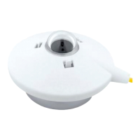
Smart Pyranometer
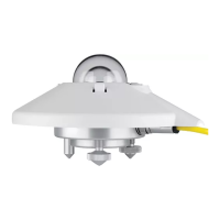
Sun screen
Optional cable, pre-wired with 8-pins connector or connector only for customer cable
Calibration certificate
Instruction sheet
Pyranometer fixing kit SMP3; 2 each of stainless steel M5 x 30, M5 x 40 and M5 x 50 mm screws, nut, flat washer
Pyranometer fixing kit SMP6 to SMP22; 2 each of stainless steel M5 x 80 mm screw, nut, flat washer, nylon insulation ring
2 Dessicant bags (SMP11 only)
.
SMP series pyranometers only require suitable sources of power and radiation (light) to operate and make measurements.
However, it is necessary to connect them to some sort of readout or data storage device in order to save the measurements, there
is no internal data memory.
5.1 Data collection
An optimal setting for the data interval is to sample every second and store one minute averages. For setting up the combination
of pyranometer and data storage please refer to the manual of the data collection device.
Take care when using the analogue output to match the output range of the pyranometer closely to the input range of the data
collection device to maximise the available resolution and minimise noise.
This can be done by determining the maximum expected analogue output of the pyranometer in your application and taking the
minimum input range of your data collection device that can just handle that signal.
5.2 Key parts of SMP series pyranometers
The detectors of the SMP’s are based on passive thermal sensing element called a thermopile. Although the detector construction
diers between models, the fundamental working principle is applicable to all SMP radiometers.
The thermopile responds to the total energy absorbed by a unique black surface coating developed by Kipp & Zonen, which is
non-spectrally selective. The thermopile warms up and the heat generated flows through a thermal resistance to a heat-sink, the
pyranometer housing. The temperature dierence across the thermal resistance of the detector is converted into a small voltage
as a linear function of the absorbed irradiance.
The rise of temperature in the thermopile is easily aected by wind, rain and thermal radiation losses to the environment (for
example, a ‘cold’ sky) and the delicate black coating must be protected. Therefore the detector of the SMP’s are shielded by two
domes (the entry-level SMP3 has only one dome to reduce size and cost). These domes allow equal transmittance of the direct
solar component for every position of the sun in the hemisphere above the detector.
A drying cartridge in the SMP11 radiometer housing is filled with replaceable silica gel and prevents condensation on the inner
sides of the domes, which can cool down considerably on clear windless nights. The other SMP’s have a sealed construction with
a non-replaceable internal drying cartridge. The internal desiccant lasts for 10 years.
5. Operation and measurement
.
5.2.1 Dome(s)
The material of the radiometer dome(s) defines the spectral measurement range of the instrument. In general 97 to 98 % of the
solar radiation spectrum will be transmitted through the domes and will be absorbed by the detector. The solar irradiance can
come from any direction within the hemisphere above the radiometer and therefore the domes are designed to minimize errors
in measurement at all incident angles (the directional response).
SMP3 pyranometers have a single 4 mm thick optical quality glass dome. The the other SMP's have one inner dome and one outer
dome. Each is 2 mm thick and of higher quality glass, with a broader spectral range and finer finishing and tolerances, than the SMP3.
The SMP22 has two high quality 4 mm quartz domes to minimize osets and widen the spectral range.
5.2.2 Detector
The thermopile sensing element is made up of a large number of thermocouple junction pairs connected electrically in series.
The absorption of thermal radiation by one of the thermocouple junctions, called the active (or ‘hot’) junction, increases its
temperature. The dierential temperature between the active junction and a reference (‘cold’) junction kept at a fixed temper-
ature produces an electromotive force directly proportional to the dierential temperature created.
This is a thermoelectric eect. The sensitivity of a pyranometer depends on the individual physical properties of the thermopile
and its construction. The sensitivity of each thermopile is unique and therefore each radiometer has an individual calibration
factor. This sensitivity is stored in the SMP pyranometer configuration memory.
The unique black coating on the top surface of the thermopile has a rough structure that eectively ‘traps’ more than 97% of the
incident radiation and heats up the hot junctions. The black-coated thermopile forms the detector, which has a spectral selectivity
of less than 2 %. This means that within the spectral range of the pyranometer, the absorption for each wavelength is equal to
within 2 %. The black absorptive coating is one of the most crucial and delicate parts of the pyranometer, Kipp & Zonen’s provides
the best possible stability over a long period of time under all meteorological circumstances.
5.2.3 Housing
The radiometer housing accommodates all the key parts of a SMP pyranometer. The anodized aluminium parts are lightweight
and give high mechanical and thermal stability to the instrument. The stainless steel fixings are isolated where necessary to
prevent electrolytic corrosion.
Due to fine mechanical construction SMP pyranometers are virtually sealed and comply with international standard IP 67. SMP’s can
be levelled with two adjustable feet using the bubble level, situated next to the dome of the instrument. For ease of maintenance
the bubble level of the SMP6 to SMP22 is visible from above without removing the snap-on white sun shield. The sun shield acts to
protect all the external parts and to reduce solar heating of the housing.
5.2.4 Drying cartridge
To keep the detector and electronics dry and to prevent condensation forming inside the domes with temperature changes a
desiccant is used to absorb humidity within the pyranometer. For the SMP’s (except SMP11) this desiccant is internal and lasts for
10 year. The desiccant will be exchanged when these instruments comes back to a Kipp & Zonen service location for re-calibration.
The SMP11 has an external drying cartridge, when fresh, the desiccant has an orange colour. After some time absorbing moisture
the colour will change to clear (transparent). At this time the silica gel is not fully saturated, but should be replaced with new
orange desiccant as soon as possible. Replacement desiccant is available through your Kipp & Zonen representative.
.
5.2.5 Cable and connector
For ease of installation and replacement during re-calibration of the radiometer, the SMP series are provided with a waterproof
cable socket fitted to the pyranometer housing. The matching waterproof plug is normally supplied pre-wired to a very high
quality yellow cable selected for low noise, very wide temperature range and UV resistance.
Cables come pre-wired to the connector plug in a range of lengths, 10 m is standard. 25 m, 50 m and 100 m lengths are also
available. The connector plug can also be supplied loose for the user to fit to their own cable.
2.2 Tools required
The tools required to fit an SMP series pyranometer to a support are a 4 mm (M5 socket head screw) Allen key and a 8 mm (M5
nut) wrench / spanner. Normally, the drying cartridge for the SMP11 should be hand-tight, but a 16 mm or 5/8” open-ended
wrench / spanner can be used to loosen it.
2.3 Location and support
The instruction sheets contain all the outline information necessary for the correct installation of the pyranometers. Further
detail for specific types of installation and application are given later in this section.
Check the condition of the desiccant in the SMP11 and replace before installation, if necessary; for example after a long storage
period. This is not required for all other SMP’s, they have an internal desiccant that is operational 10 years after the last
calibration date as mentioned on the instrument label and calibration certificate.
When using the digital output it might be convenient to set the Modbus® address prior to visiting the site, otherwise a computer
and RS-485 / USB converter may be required during installation.
2.4 Installation for measurement of horizontal global irradiance
The following steps must be carefully taken for optimal performance of the instrument.
2.4.1 Location
Ideally, the site for the radiometer should be free from any obstructions to the hemispherical view from the plane of the detector.
If this is not possible, the site should be chosen in such a way that any obstruction over the azimuth range between earliest
sunrise and latest sunset should have an elevation not exceeding 5 ° (the apparent sun diameter is 0.5 °).
This is important for an accurate measurement of the direct solar radiation component. The diuse solar radiation is less
influenced by obstructions near the horizon. For instance, an obstruction with an elevation of 5° over the whole azimuth range
of 360 ° decreases the downward diuse solar radiation by only 0.8 %.
It is evident that the radiometer should be located in such a way that a shadow will not be cast upon it at any time (for example
by masts or ventilation ducts). Note that hot exhaust gas (> 100 °C) will produce some radiation in the spectral range of the
radiometer and cause an oset in the measurements. The radiometer should be distant from light-coloured walls or other
objects likely to reflect sunlight onto it, or emitting short-wave radiation.
The radiometer should be readily accessible for cleaning the outer dome, checking that it is level and inspecting the desiccant.
.
2.4.2 Mounting
The SMP pyranometer is provided with two holes for 5 mm bolts. Two nylon insulation rings and two each of stainless steel bolts,
washers and nuts are provided in the fixing kit. The pyranometer should first be secured lightly with the bolts to a solid and
stable mounting stand or platform as shown below. The nylon insulators are important to prevent corrosion between the screws
and the pyranometer housing.
The mounting stand temperature may vary over a wider range than the air temperature. Temperature fluctuations of the
pyranometer body can produce oset signals, therefore it is recommended to isolate the pyranometer thermally from the
mounting stand by placing it on its three feet. Ensure that there is a good electrical contact with the ground to conduct away
currents in the cable shield induced by lightning.
Note After recalibration and/or reinstallation ensure that the nylon insulators are refitted.
2.4.3 Orientation
In principle no special orientation of the instrument is required, although the World Meteorological Organisation (WMO) recommends
that the signal lead (connector) is pointed towards the nearest pole, to minimise heating of the electrical connections. This is also
where any mounting pole, or other support, should be located in order that shadows do not fall on the instrument.
2.4.4 Levelling
Accurate measurement of the global radiation requires proper levelling of the detector surface. Level the instrument by turning
the two adjustable feet to bring the bubble of the spirit level centrally within the marked ring. For easy levelling, first use the
screw nearest to the spirit level.
Note It is ideal that the bubble should be completely within the marked ring. However, in fact, the pyranometer is level
within the specified accuracy when the bubble is at least half within the ring.
2.4.5 Securing
Secure the pyranometer tightly with the two stainless steel bolts. Use the two nylon insulators to avoid contact between the
aluminium body and the steel screws. Ensure that the pyranometer maintains the correct levelled position when it is tightened.
.
2.4.6 Fitting the connector and cable
Locate the plug correctly in the radiometer socket, it only fits one way, and push it in. Screw the plug locking ring hand-tight.
Over-tightening may damage the waterproof seal. Secure the cable so that it cannot blow in the wind or cause a shadow on the
instrument.
Note The cable should be arranged with a curve below the instrument so that water drips o, rather than running along
the cable up to the connector.
2.4.7 Fitting the sun shield
Finally, clip on the sun shield to prevent excessive heating of the radiometer body. The bubble level is visible through the top
of the sun shield for routine checks and the shield ‘tail’ helps to protect the connector.
2.5 Installation for measurement of tilted global irradiance
When a pyranometer is mounted on a large flat tilted surface the temperature of this surface can rise considerably (more than
10 °C) above air temperature. It is advised to pre-adjust the levelling feet on a horizontal surface for easy mounting of the
instrument parallel to the inclined surface. It improves the measurement accuracy when the body is thermally isolated by its
feet from the surface. This promotes thermal equilibrium between the dome(s) and the housing and decreases zero osets.
For accurately and securely fixing a pyranometer at an angle to a surface an adjustable tilt mounting kit is available. See Accessories
in chapter 3.
2.6 Installation for measurement of reflected global irradiance
In the inverted position the pyranometer measures reflected global radiation. The
height above the surface (H) depends upon its roughness. The WMO recommends a
height of 1 m to 2 m above a uniform surface covered by short grass.
The mounting device should not interfere significantly with the field of view of the
instrument. The mounting plate above the pyranometer prevents excessive heating of
the housing by downwards solar radiation and. The glare screen has an angle of 5 °
and is fitted to the pyranometer to prevent direct illumination of the domes by the sun
at sunrise and sunset. It is available as an accessory kit for all SMP’s except the SMP3.
Thermal oset signals generated in the pyranometer are 5 times more significant
in the measurement of reflected radiation due to the lower irradiance level.
The mast shown intercepts a fraction D/2πS. of the radiation coming from the
ground. In the most unfavourable situation (sun at zenith) the pyranometer
shadow decreases the signal by a factor R2/H2.
As a guide, a black shadow below the pyranometer with a radius of 0.1 x H decreases the signal by 1%, and 99 % of the signal
will originate from an area with a radius of 10 x H.
2.7 Installation for measurement of albedo
An albedometer consists of two identical pyranometers that measure the
incoming global solar radiation and the radiation reflected from the surface
below. Albedo is the ratio of the two irradiances, and varies from 0 (dark)
to 1 (bright).
Two SMP3’s can be mounted back to back with the standard fixing kit, and the
accessory mounting rod screwed into one of them, to make an albedometer.
For all other SMP’s a mounting plate is required. The CMF1 mounting plate is
used for unventilated SMP’s and the CMF4 for ventilated instruments. There
is no ventilation unit for the SMP3.
The requirements for installation of the upper pyranometer are the same as
for horizontal global irradiance. The requirements for installation of the
lower pyranometer and mast are the same as for reflected global irradiance.
2.8 Installation for measurement of horizontal diffuse irradiance
For measuring the diuse radiation from the sky, the direct solar radiation
must be blocked from the pyranometer dome(s).
A static shadow ring can be used to intercept the direct solar radiation. This
requires frequent manual adjustment as the sun’s arc in the sky changes. At
times the shadow ring also intercepts a significant proportion of the diuse
sky radiation. Therefore, post-processing of the recorded data is necessary to
correct for this.
Kipp & Zonen produces a universal shadow ring, model CM121, which is
suitable for use at all latitudes.
The alternative to a shadow ring is to use a two-axis automatic sun tracker,
such as one of the models from Kipp & Zonen. The sun tracker uses location
and time information to calculate the position of the sun and point at it
accurately under all weather conditions.
The sun tracker can be fitted with a small disk or sphere mounted on an
articulated shading assembly. The shadow of the disk or sphere is adjusted to
cover the pyranometer dome(s) completely and it will then be shaded correct-
ly throughout the year without adjustment.
2.9 Electrical connections
As standard SMP pyranometers are supplied with a waterproof connector pre-wired to 10 m of high quality yellow cable with 8
wires and a shield covered with a black sleeve. Longer cables are available as options. The colour code of the wires and the
connector pin numbers are shown below and on the instruction sheet.
Special attention is needed to prevent power or ground loops when connecting the SMP to multiple readout devices.
Connecting the RS-485 to a grounded circuit and the analogue output to a floating circuit can cause unacceptable
ground loops. This may cause dierential voltages outside the SMP specifications and will damage the unit. We
recommend using either the analogue or the digital output but not both. The maximum dierential between either
of the Modbus® RS-485 lines (yellow and grey) and the power ground / RS-485 common line (black) is 70 VDC.
First connect all wires before plugging into the radiometer
The shield of the cable is connected to the aluminium radiometer housing through the connector body. Preferably,
secure the radiometer with its levelling screws on a metal support with a good connection to ground (e.g. by using
a lightning conductor) and do not connect the cable shield at the readout end.
If there is no good ground connection at the pyranometer, the shield at the cable end should be connected to ground
at the readout equipment. Lightning can induce high voltages in the shield but these will be led o at the pyranometer
or readout equipment.
Note Long cables may be used, but the cable resistance must be smaller than 0.1 % of the impedance of the readout
equipment for the analogue outputs and may aect the baud rate of the RS-485 digital connection.
2.9.1 Power connection
The minimum power supply voltage for SMP pyranometers is 5 VDC. However, for optimal performance it is advised to use
12 VDC, especially when long cables are used. 5-volt power can only be used in combination with a short cable, maximum 10 m.
It is advised to protect the output of the power supply with a fast blowing fuse of maximum 250 mA rating.
Typical power consumption SMP-V for maximum output (1 V)
5 VDC 50 mW (approx. 10.0 mA)
12 VDC 55 mW (approx. 4.5 mA)
24 VDC 60 mW (approx. 2.5 mA)
.
Maximum power consumption 65 mW at the highest input voltage.
Maximum input current 12.5 mA at the lowest input voltage.
Maximum inrush current 200 mA.
Typical power consumption SMP-A for max output (20 mA)
5 VDC 77 mW (approx. 28 mA with 100 Ω load resistor)
12 VDC 83 mW (approx. 24 mA with 100 Ω load resistor)
24 VDC 100 mW (approx. 6 mA with 100 Ω load resistor)
The above mW values represent the dissipation within the SMP-A. For the total power the energy in the load resistor has to
be added.
For supply voltages below 12 Volts or above 20 Volts it is advised to use a load resistor of less than 500 Ω to keep the power
consumption as low as possible.
2.9.2 Data connection
Connection to a Personal Computer by Universal Serial Bus (USB)
The connection depends on the use of a RS-485 to USB converter.
The converter must have galvanic isolation between the inputs and outputs to prevent possible damage to the SMP
digital interface. This is particularly an issue with portable computers (laptops, etc.) in which the power supplies
can generate large voltage spikes.
A suitable converter is the model USOPTL4 from B & B Electronics. One end has the USB connector to the PC the other end has
a connector with screw terminals for the instrument wires. This RS-485 converter is powered from the USB interface, so no
additional power adaptor is necessary.
*Note Switches on the converter should be set for RS-485, 2-wire operation and Echo o.
Connection to a RS-485 Network
The digital interface can be connected to a 2-wire RS-485 network as shown below.
The slaves and master may be a SMP pyranometer or other devices. If a SMP pyranometer is the last device on the network a
line terminator (LT), consisting of a 120 Ω or 150 Ω resistor, must be connected between terminals A/A'/- and B/B'/+. Never
place this line termination on the derivation cable. It is also required to install the pull up and pull down resistors as shown.
The value of these resistors must be between 650 Ω and 850 Ω.
2.9.3 Analogue voltage output
The SMP-V (voltage output versions) have been factory set such that an output of 0 Volts represents -200 W/m² (this will never
be reached in practice), and the full-scale output of 1 Volt represents 2000 W/m².
The voltage output range in W/m² can be changed by the user with the supplied PC software. The maximum recommended
irradiance for the SMP3 and SMP6 is 2000 W/m² and for all other SMP’s it is 4000 W/m².
The measurement range must start from a negative value in order to show (small) negative readings, for example night-time
osets, because the analogue output itself cannot go negative. For the default setting of 0 to 1 Volt representing -200 to 2000
W/m² the range is actually 2200 W/m² with a zero oset of 200 W/m².
The irradiance value (
E
solar
) for the default setting can be simply calculated as shown below.
E
solar
= Solar radiation [W/m²]
V = Output of radiometer [Volt]
If the pyranometer is used in atmospheric conditions it is advised to keep the range as factory set.
2.9.4 Analogue current output
The SMP-A (current output versions) have been factory set such that an output of 4 mA represents 0 W/m² and the full-scale
output of 20 mA represents 1600 W/m².
The current output range in W/m² can be changed by the user with the supplied PC software. The maximum recommended
irradiance for the SMP3 and SMP6 are 2000 W/m² and for all other SMP’s it is 4000 W/m².
Negative inputs will make the output go below 4 mA and no zero oset is needed.
For the default setting of 4 to 20 mA representing 0 to 1600 W/m², each mA represents 100 W/m².
The irradiance value (
E
solar
) for the default setting can be simply calculated as shown below.
E
solar
= Solar radiation [W/m²]
mA = Output of radiometer [mA]
2.9.5 Recommended cable types
Where cables need to be extended, or the customer prefers to provide their own cables, they should be suitable for outdoor used
and UV resistant.
Recommended types
RS-485 Ethernet CAT 5 shielded twisted pair (STP)
0 to 1 V Shielded 2-core signal cable
4 to 20 mA Shielded twisted pair control cable
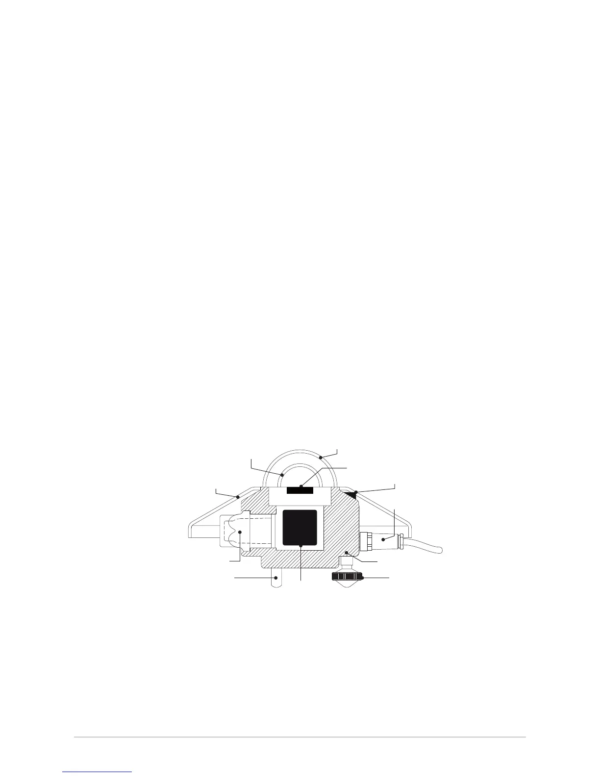
smart interface
drying cartridge (SMP11 only)
inner glass dome
outer glass dome
housing
detector
sun shield
bubble level
connector
fixed foot adjustable feet
27
 Loading...