.
Explanation of the received bytes:
01 = MODBUS address
04 = read input registers
10 = number of received data bytes
00 01 = operational mode (mode 1)
00 00 = status flags (none)
00 00 = scale factor = 0 = 1x
03 E5 = 997 decimal = sensor 1 data in W/m²
03 E5 = 997 decimal = raw sensor 1 data in W/m²
00 00 = 0 = standard deviation sensor 1
00 F8 = 248 = 24.8°C.
00 EA = 234 = 23.4 Volt
66 12 = MODBUS checksum (CRC16)
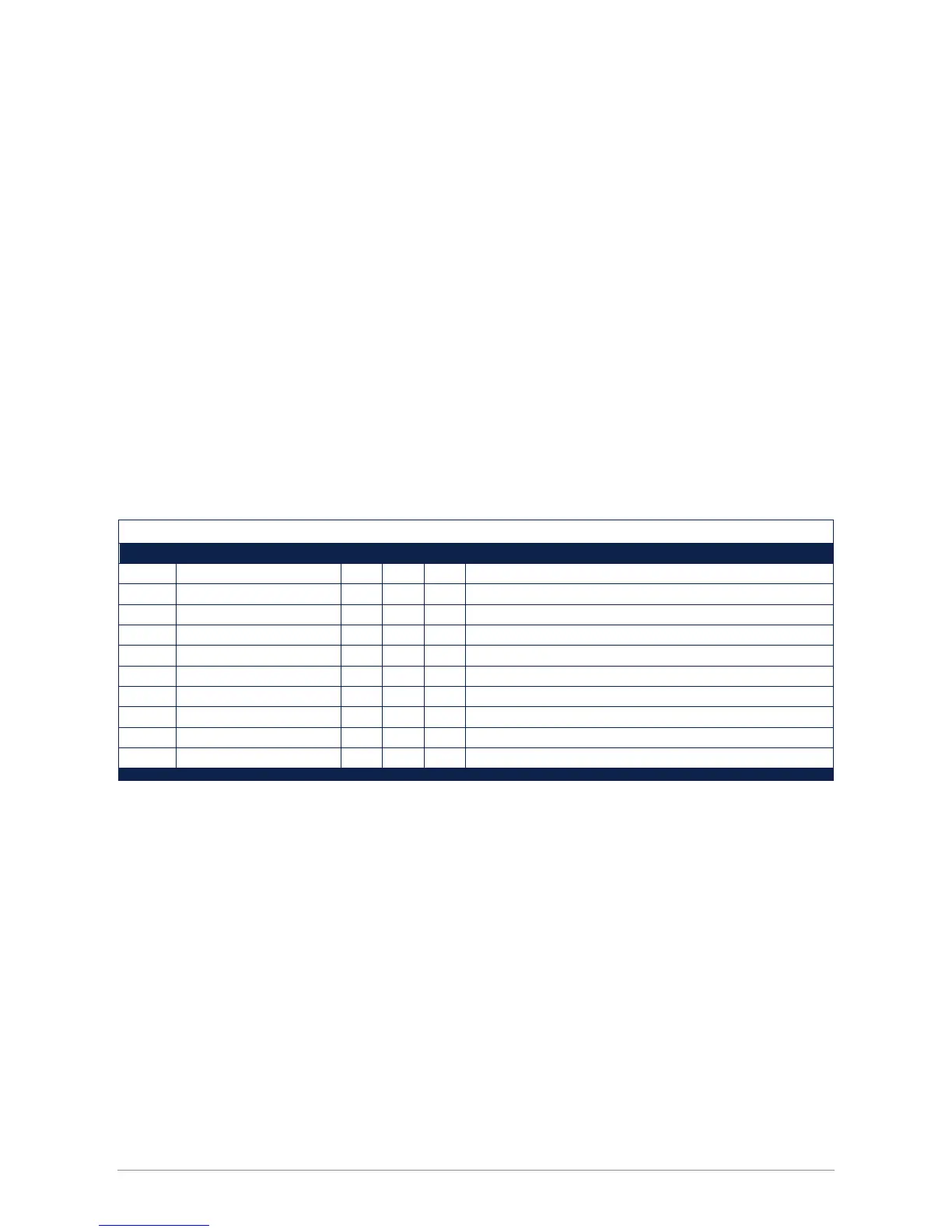
A.5 Discrete inputs
A discrete input can be true or false. A discrete input is read only; a coil can be read or written.
Status indicators
Input Parameter R/W Def. Mode Description
0 IO_FALSE R 0 All Always false (for testing only)
1 IO_TRUE R 1 All Always true (for testing only)
2 IO_VOID_DATA_FLAG R * All Void signal, 1=unstable signal, temperature too low or too high
3 IO_OVERFLOW_ERROR R * All Overflow, signal out of range
4 IO_UNDEFLOW_ERROR R * All Underflow signal out of range
5 IO_ERROR_FLAG R * All General hardware error (set if one of the H/W error flags is set)
6 IO_ADC_ERROR R * All Hardware error A/D converter
7 IO_DAC_ERROR R * All Hardware error D/A converter
8 IO_CALIBRATION_ERROR R * All Calibration checksum error
9 IO_UPDATE_FAILED R * All Update calibration parameters failed
Legend
Input Discrete input Modbus® discrete input 0 is the first discrete input
Coil Modbus Coil A coil can be read or written.
Parameter Name Name of the register
R/W Read write R Read only
R/W Read/write
Def Default value default value at power on (0, 1 or *) * = undefined
Mode operation mode N available in normal mode
S available in service mode
C available in calibration mode (not for users)
F available in factory mode (not for users)
All available in all modes
Inputs can be read in all modes but some coils can’t be written in normal mode or service mode.
46
 Loading...