PT568 Service Manual
7
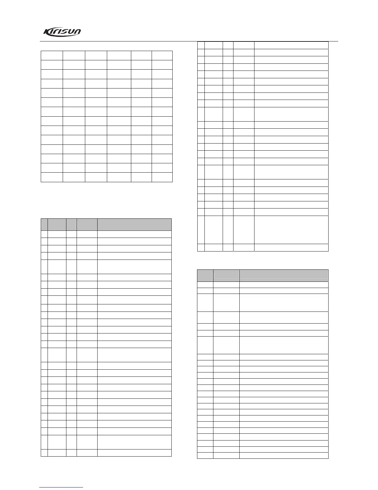
Table 3.2 DCS Codes
023 114 174 315 445 631
025 115 205 331 464 632
026 116 223 343 465 654
031 125 226 346 466 662
032 131 243 351 503 664
043 132 244 364 506 703
047 134 245 365 516 712
051 143 251 371 532 723
054 152 261 411 546 731
065 155 263 412 565 732
071 156 265 413 606 734
072 162 271 423 612 743
073 165 306 431 624 754
074 172 311 432 627
3.8 Semiconductor Data
Refer to table 3.3 for descriptions of each pin.
Table 3.3 Definition of CPU Pins
No. Port name
Pin
Name
I/O Function
1 NC NC
2 AFCO2 P35 O Audio frequency switch 2
3 GLED P33 O Green LED switch
4 PTT P34 I [PTT] input
5 MODE I
Connect the 4.7K resistor with VCC,
programming test point
6 VDEVC2 P43 O VHF deviation switch 2
7 VDEVC1 P44 O VHF deviation switch 1
8 RST I Reset input, programming test point
9 XOUT O
10 VSS I GND, programming test point
11 XIN I Oscillator (7.3MHz)
12 VCC I 5V CPU power input, programming test point
13 SHIFT P27 O Clock beat shift. H: On
14 VCCN P26 O(PWM) Frequency stability output
15 TO P25 O(PWM) QT/DQT output
16 WNTC P24 O
Wideband/Narrowband control
H: Wideband, L: Narrowband
17 APC P23 O(PWM) TX: Automatic power control output, RX: 0
18 TUNE P22 O(PWM) TX: 0 RX: BPF tuning output
19 BEEP P21 O(PWM) BEEP/DTMF output
20 SDA P20 I/O EEPROM data line
21 ENC0 P17 I Encoder input
22 ENC2 P16 I Encoder input
23 ENC3 P15 I Encoder input
24 ENC1 P14 I Encoder input
25 SCL P13 O EEPROM clock line
26 NC NC
27 UL P45 I
PLL circuit unlock detect pin
H: locked, L: unlocked
28 TXD P66 O RS-232C output, programming test point
29 RXD P67 I RS-232C input, programming test point
30 CK P12 O PLL clock output
31 DT P11 O PLL data output
32 LE P10 O PLL IC enable pin, H: locked
33 RX P31 O Receiving enable
34 BUSY_V P30 O Busy signal of voice annunciation IC
35 DATA_V P65 O Data of voice annunciation IC
36 SCLK_V P64 O Clock of voice annunciation IC
37 RLED P63 O Red LED control, H: On
38 NC P07 I(A/D0)
Connect the pull-up resistor with VCC, and
connect the pull-down resistor with VSS
39 NC NC
40 NC NC
41 TI P06 I(A/D1) QT/DQT signal input
42 BUSY P05 I(A/D2) Busy signal input
43 BATT P04 I(A/D3) Battery voltage detect
44 VREF I Connect with VCC
45 SAVE P60 O
Battery saving control, H: supply power, L:
power saving
46 MUTE P62 O Mute control H: Mic mute L: audio mute
47 5RC P61 O Receiving power control L: On
48 KEYIN P03 I(A/D4) Programmable key P1, P2, P3 detect
49 5TC P02 O Transmitting power control, H: On
50 RLED P01 O Red LED switch
51 AC P00 O
Alarm switch control, H: controlled by volume
switch
Radio should be in low level in emergency
alarm
52 AFCO1 P37 I Audio control switch 1
Table 3.4 Function Description of Semiconductor Components
Position
Mark
Model Function Description
IC1 MB15E03 Frequency synthesizer
IC4 NJM2904 APC, voltage comparison, driving
IC5 TA31136 Rx second local oscillation, second IF
amplification, limitation, demodulation, and
noise amplification
IC6 NJM2902 Amplification and filtering of demodulation
signal of receiver.
IC7 NJM2902 MIC amplification, limitation and filtering
IC8 TDA8541 Audio frequency power amplification of receiver
IC9 AT24C08 E
2
PROM, memorizes channel frequency data,
function setting parameters and adjusting status
parameters
IC10 R5F212A8 MCU
IC11 PST9140NR MCU reset circuit
IC12 HT7150-1 LDO, low-power voltage regulator
IC15 W588A080 Voice storage IC
Q2 2SC5108 First amplification of transmitter
Q3 2SC3356 Second amplification of transmitter
Q4 2SC5108 VCO buffer amplifier
Q5 2SC5108 VCO buffer amplifier
Q6 2SC4617 VCO power supply filter
Q7 2SC4738 Noise amplifier
Q9 2SC4617 Audio frequency signal amplification of receiver
Q10 2SC1623 5V voltage regulation output current stretching
Q11 2SK3476 Transmitter final power amplification
Q12 RD01MUS1 Transmitter power amplification driving
Q17 DTA144EE APC output switch
Q19 3SK318 First mixer
Q20 3SK318 Receiver high power amplifier