Remove the DC compartment cover by removing the two screws located on the top surface of
the unit.
Keep the connection between the House Battery bank and the charger as short as possible.
Connect one end of the positive wire (red wire) to the CH1 (House Battery bank) of charger
positive terminal with torque 4.0-5.0 N-m (35-45 lb-in) and the other end to the over current
protection device, then the DC disconnect device. Do not over tighten as this may result in
damage to the charger.
Connect another wire from the DC disconnect device to the House Battery Bank.
Prepare the negative (black) wire and connect between the CH1 negative terminal of the
charger and the negative terminal of the House Battery bank.
Use the same connection method to make connection on CH2 (Solar Array/Panel) and CH3
(Alternator/Start battery). See more details below on Battery Wiring.
Place the DC Compartment cover back to the original position and secure the cover using the
two screws provided.
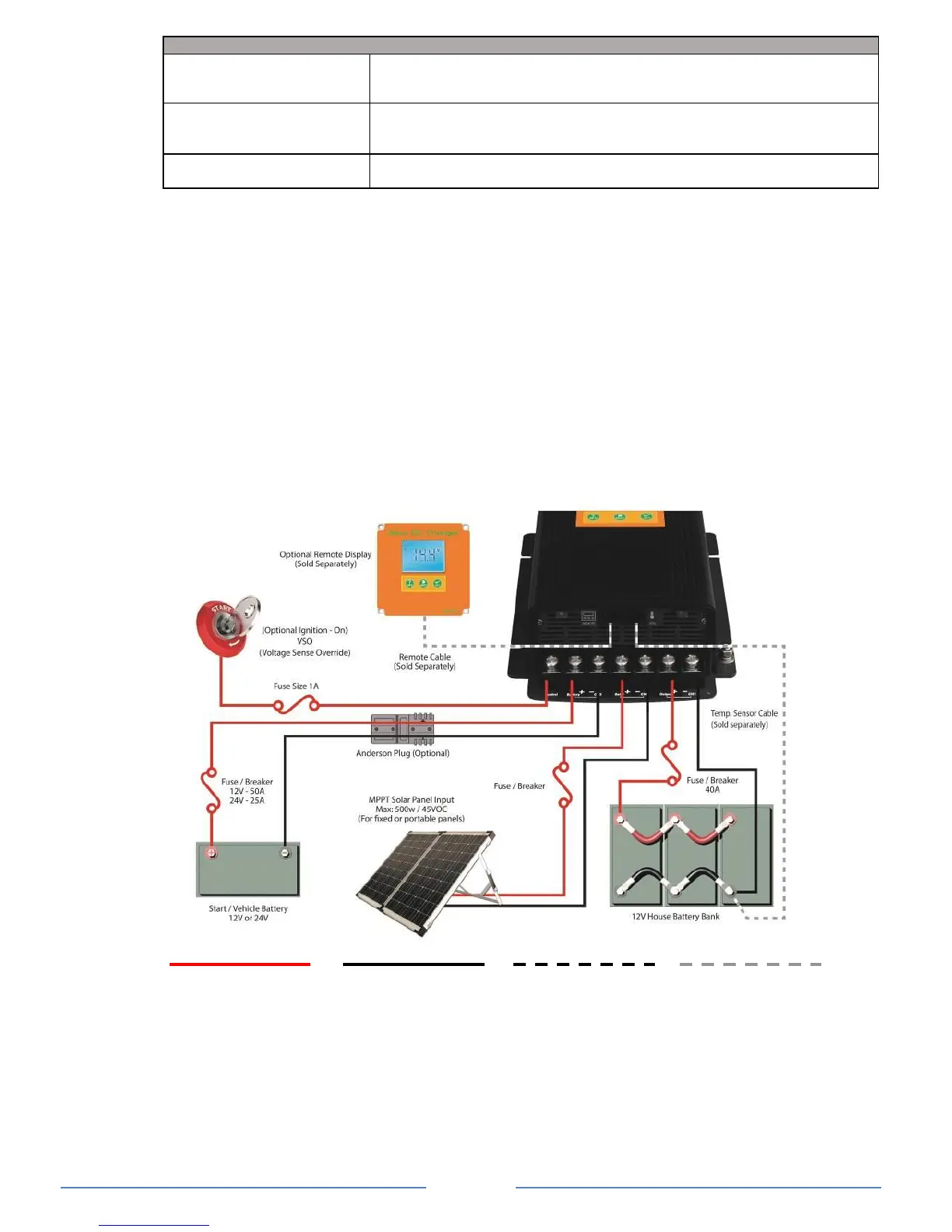
Battery Wiring: Connecting the Batteries the Right Way
POSITIVE WIRE NEGATIVE WIRE
Note: This diagram is for a reference only. No cables, fuse/breakers, batteries or solar panels are
supplied with this unit. Local rules and regulations should be followed when installing this unit.
Battery Temperature Sensor Port Connection (optional BTS sold separately)
To install the Battery Temperature Sensor (BTS), simply connect the RJ12 plug from the
sensor to the RJ12 Temperature Sensor Port located next to the Remote Display Port.
On the temperature sensor end, simply connect the ring terminals to the negative terminal of
the main house battery bank.
NOTE: For lithium battery, the temperature sensor is not required for these applications.