drip protection.
Use the base of the charger as a mounting template to mark the positions of the fixing screws.
Drill the 4 fixing holes and place the Charger in position and fasten the unit to the mounting
surface.
Note: The charger is designed to be permanently mounted.
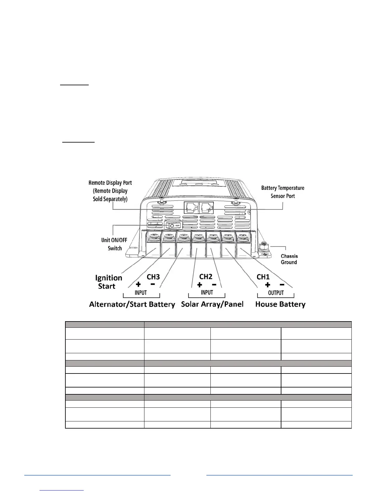
5. CONNECTING THE CHARGER
Chassis Ground Connection:
DANGER: The unit chassis has to be grounded properly. Never operate the Charger
without proper grounding. Failure to do so will result in death or serious injury. Ground
connection to the charger must comply with all local and application-specific codes and
ordinances.
Connect the unit’s chassis ground to the common ground point through the ground stud
“Chassis Ground” located near one of the unit mounting slots.
DC Inputs and Output Wiring:
WARNING: The DC wiring used must be of appropriate size. An individual over-current
protection device usually within 7 inches (17.8cm) of each battery bank is required. A DC
disconnect switch is also recommended. Both devices must be rated for DC voltage and current
and be rated to withstand the short circuit current available from the connected battery bank.
Both devices must match with the size of the DC wiring.
Recommended Cable Length, Size and Fuse Protection:
Note: Cable size quoted is one way from battery to device, the suggested cable size is calculated with
return run.
1) If solar panels are wired in series (increased voltage), then typically 1 x 4mm
2
cable run per series
string is suitable.
2) Based on 3% voltage drop