6. Placecooktoprightsideupintothecutout.
NOTE:Makesurethatthefrontedgeofthecooktopis
paralleltothefrontedgeofthecountertop.Ifrepositioningis
needed,liftentirecooktopupfromthecutouttoavoid
scratchingthecountertop.
7. Connectblowerexhaustscrolltoducting.
8. Useventclampstosecuretheductingtotheblowerexhaust
scroll.
9. Reinstallgreasefilter.
10.Reinstallventgrille.
_G_ B_( W/@_o( ?_ _o_ _
IMPORTANT: The following additional steps must be performed
if the product is being installed in peninsula or island cabinetry.
The blower exhaust scroll is shipped from the factory set to
exhaust straight out the back of the cabinet through an exterior
wall.
l
A B
E
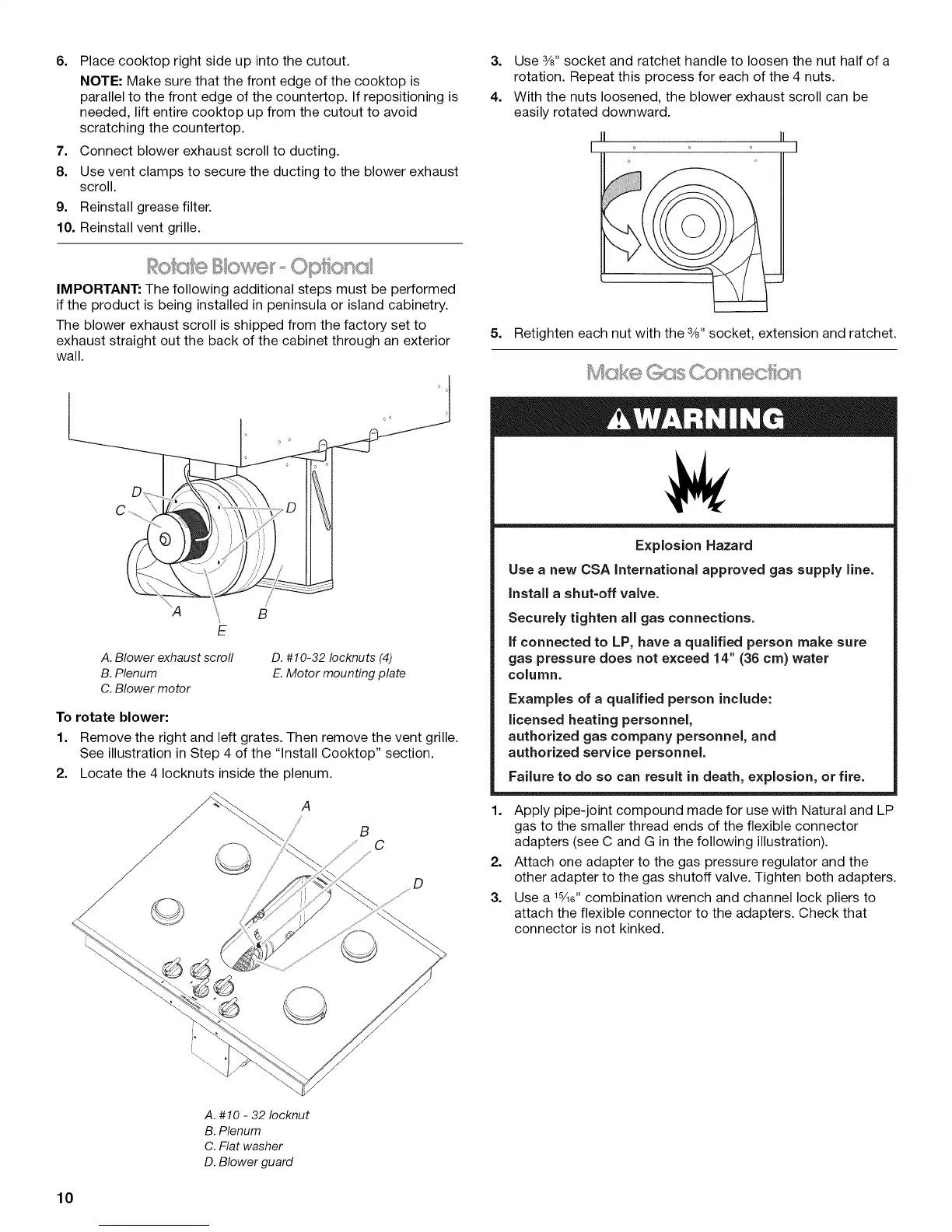
A. Blower exhaust scroll
B. Plenum
C. Blower motor
D. #10-32 Iocknuts (4)
E. Motor mounting plate
To rotate blower:
1. Remove the right and left grates. Then remove the vent grille.
See illustration in Step 4 of the "Install Cooktop" section.
2. Locate the 4 Iocknuts inside the plenum.
3. Use 3/8"socket and ratchet handle to loosen the nut half of a
rotation. Repeat this process for each of the 4 nuts.
4. With the nuts loosened, the blower exhaust scroll can be
easily rotated downward.
5. Retighten each nut with the 3/8"socket, extension and ratchet.
Explosion Hazard
Use a new CSA International approved gas supply line.
Install a shut=off valve.
Securely tighten all gas connections.
if connected to LP, have a qualified person make sure
gas pressure does not exceed 14" (36 cm) water
column.
Examples of a qualified person include:
licensed heating personnel,
authorized gas company personnel, and
authorized service personnel.
Failure to do so can result in death, explosion, or fire.
1. Apply pipe-joint compound made for use with Natural and LP
gas to the smaller thread ends of the flexible connector
adapters (see C and G in the following illustration).
2. Attach one adapter to the gas pressure regulator and the
other adapter to the gas shutoff valve. Tighten both adapters.
3. Use a _3i_e"combination wrench and channel lock pliers to
attach the flexible connector to the adapters. Check that
connector is not kinked.
A. #10 - 32 Iocknut
B. Plenum
C. Flat washer
D. Blower guard
10