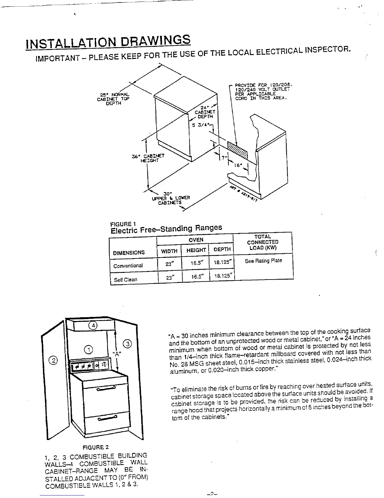
INSTALLATION DRAWINGS
IMPORTANT - PLEASE KEEP FOR THE USE OF THE LOCAL ELECTRICAL INSPECTOR.
1_0/_40 VOLT OUTLET
PER APPLICABLE
CCRO _N T_I$ AREA.
36" 82
HEIGHT I?
CABINETS
FIGURE 1
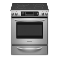
Electric Fre_--Standing Ranges
OVEN TOTAL
CQNNECTED
DIMEN$ION_ WIDTH HEIGHT DEPTH LOAD(KW]
C(_nventionat 23_' 16.5" 18.'_25" _ee Reting Plate
Self C_ean 23" I 16.5" 18.125"
I
I
_[ "A= 30 inches minimum clearance betweenthe tao of thecooking surface
andthe bottom of an unprotected wood ormetalcabinet." or "A = 24.inches
,, minimum when bottom of wood or metal cabinet is protected by not less
Q than 1/4_inch thick flame-retardant millboard covered with not less than
No.28 MSG sheetsteel, 0.015-inch thickstainless steet,0.024.--4richthick
aluminum, or 0.020-inch thick copper."
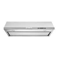
_o eliminate the riskof burns or fire byreaching over heatedsurfaceunits,
i cabinet s_orage"spac_,ccated above the surfac_ounits shouldbe avoided,if
cabinet storage is to be provided, the risk can be reduced by installing a
range hoodthatprojects horizontallya minimumof5inches beyondthebot-
_ tom of the cabinets."
FIGURE 2
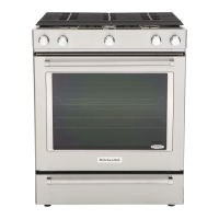
1, 2, 3 COMBUSTIBLE BUILDING
WALLS--.4 COMBUSTIBLE WALL
CABINET-RANGE MAY BE IN-
STALLED ADJACENTTQ (0" FROM)
COMBUSTIBLE WALLS 1, 2 & 3.