High Power Amp Essentials
www.kitronik.co.uk/2143
Now solder the two electrolytic capacitors. The capacitors have text printed on the side that
indicates their value. The 10µF capacitors should be soldered into C4 on the PCB and the 470µF
capacitor should be soldered into C1. Make sure that the capacitors are the correct way around.
The capacitors have a ‘-’ sign marked on them, which should match the same sign on the PCB.
There are three terminal blocks that allow the power and speaker wires to be attached to the
PCB. These go into the PCB where it is labelled ‘POWER’, ‘OUT1’ and ‘OUT2’. Make sure that they
face towards the edge of the PCB.
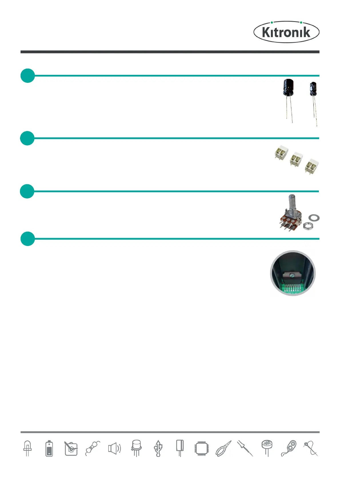
Solder the dual potentiometer into the PCB where it is labelled R4. Make sure that the volume
knob is facing away from the PCB.
The next step is to add the heat sink and ampli®er IC. The best way to do this is in the
following order:
Solder the heat sink to the PCB. The heat sink must be orientated so that it matches
the outline on the PCB. As the heat sink is a very large part, it may take longer than
normal for it to be soldered. If you have a temperature controlled soldering iron, turn
it up to full just for the heat sink.
Insert the ampli®er IC into the PCB and attach it to the heat sink by using the nut and bolt.
Solder the IC pins to the PCB.
SOLDER THE ELECTROLYTIC CAPACITORS
SOLDER THE DUAL POTENTIOMETER
ADD HEAT SINK AND AMPLIFIER IC