D
GB
24
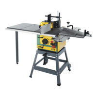
6. INBETRIEBNAHME DER MASCHINE
3. Montage des Schlittens zum Zapfenschneiden (10)
4. Montage der Schlittenschiene (11)
- Schieben Sie die beiden Profile (D) der Schlittenschiene unter
den Maschinentisch (V1).
- Ziehen Sie die 4 Schrauben fest an.
- Der Schlitten gleitet bis zu den Enden der Schiene.
-Er besteht aus einem beweglichen Anschlag und einem Län-
genbegrenzungsanschlag.
- Montieren Sie zunächst 2 Schrauben in die Löcher an der
Maschinenkante (E1).
- Schieben Sie die Schiene so auf die Tischkante, dass die
Schraubenköpfe sich im Hohlraum der Schiene bewegen (siehe
Detail).
- Ziehen Sie die beiden Muttern fest an.
g. Montage des Sonderzubehörs
2. Montage der Tischverlängerung (09)
- Schieben Sie die beiden Profile der Tischverlängerung entlang
dem Maschinentisch.
- Ziehen Sie die 6 Schrauben fest an.
- Die 2 Platten der Tischverlängerung gleiten auf den Profilen.
- Der Profilanschlag verriegelt sich mit dem Knopf (C1).
6. PUTTING THE MACHINE INTO OPERATION
3. Assembly of the tenoning carriage (10)
4. Fitting the carriage rail (11)
g. Fitting the optional equipment
2. Fitting the table length extension (09)
- Slide the 2 profiles of the table length extension along the
machine table.
- Firmly tighten the 6 bolts.
- The 2 plates of the table extension glide on the profiles.
- The profile guide is locked with the knob (C
1).
- Slide the 2 profiles (D) in the carriage rail below the machine
table(V
1).
- Firmly tighten the 4 bolts.
- The carriage glides to the ends of the rail.
- It consists of a movable fence and a length limiting stop.
- First put the 2 bolts into the holes on the machine edge (E
1).
- Slide the rail onto the table edge in such a way that the bolt
heads move in the hollow space of the rail (see detail).
- Firmly tighten the 2 nuts.