ENGLISH
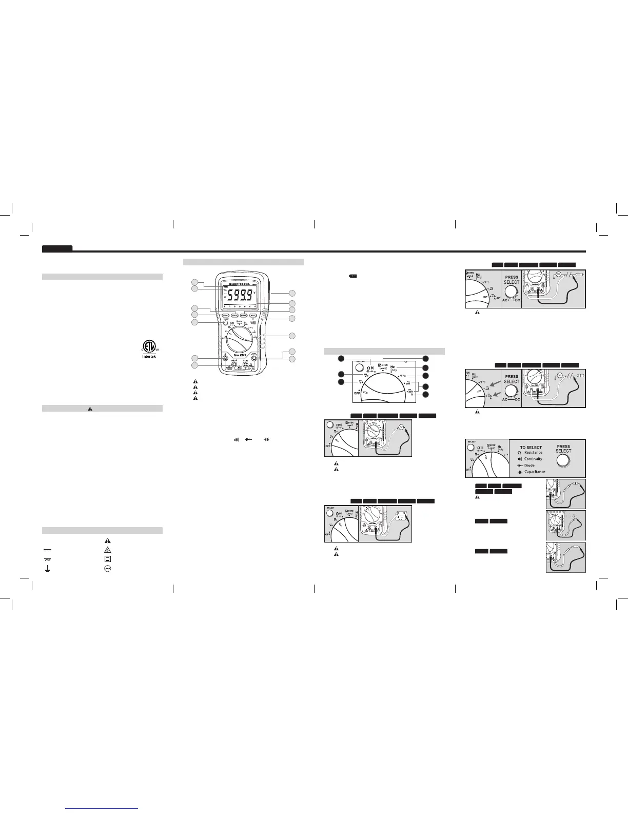
FEATUREDETAILS
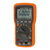
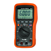
MM6000
InstructionManual
GENERALSPECIFICATIONS
The Klein Tools MM6000 is a True RMS, auto-ranging multimeter.
It measures AC/DC voltage, low impedance voltage, AC/DC current,
resistance, capacitance, frequency, duty cycle, and temperature. It can also
test diodes and continuity.
• OperatingAltitude:6562 ft / 2000 m
• RelativeHumidity:<75%
• OperatingTemperature:O°C/32°F to 45°C/113°F
• StorageTemperature:-20°C/ -4°F to 60°C/140°F <80% R.H.
• AccuracyTemperature:18°C/64°F to 28°C/82°F
• TemperatureCoefcient: 0.1*(specified accuracy)/ °C
• SamplingFrequency:3 samples per second
• Dimensions: 7” x 3.5” x 1.875”
• Weight:14 oz.
• BatteryLife:160 Hours
• Calibration:Accurate for one year
• Accuracy:± (% of reading + # of least significant digits)
• CATRating:CAT III 1000V, CAT IV 600V
• Certications:Conforms to UL Stds 61010-1 & 61010-2-030.
Certified to CAN/CSA C22.2 No.61010-1, 61010-2-030,
IEC 61010-2-030:2010 MOD, ANSI/ISA-61010-2-030 (82.02.03).
• PolutionDegree:2
• CountryofOrigin:USA (of US and imported parts)
WARNINGS
To ensure safe operation and service of the tester, follow these instructions.
Failure to observe these warnings can result in severe injury or death.
• Before each use, verify meter operation by measuring a known
voltage or current.
• Never use the meter on a circuit with voltages that exceed the
category based rating of this meter.
• Do not use the meter during electrical storms or in wet weather.
• Do not use the meter or test leads if they appear to be damaged.
• Ensure meter leads are fully seated, and keep fingers away from the
metal probe contacts when making measurements.
• Do not open the meter to replace batteries or fuses while the probes
are connected.
• Use caution when working with voltages above 60V DC or 25V AC
RMS. Such voltages pose a shock hazard.
• To avoid false readings that can lead to electrical shock, replace
batteries if a low battery indicator appears.
• Unless measuring voltage or current, shut off and lock out power
before measuring resistance or capacitance.
• Always adhere to local and national safety codes. Use individual
protective equipment to prevent shock and arc blast injury where
hazardous live conductors are exposed.
SYMBOLS
~
ACAlternatingCurrent WarningorCaution
DCDirectCurrent DangerousLevels
DC/ACVoltageorCurrent DoubleInsulatedClassII
Ground ACSource
C
E
A
G
F
D
H
J
I
M
L
K
N
B
5
1
8
3
4
6
7
2
1. ACVoltage:<1000V.(LOWZ)<600V
Features:
MAX/MINRANGEHOLDREL
DONOTattempttomeasuremorethan1000V.
DONOTuse(LOWZ)modeatvoltagesgreaterthan600V.
• Use Low Impedance (LOW Z) mode to reduce ghost voltages.
• Rotate selector to "AC" Voltage position.
• Attach RED lead to “V” input, BLACK lead to COM.
2. DCVoltage:<1000V.(LOWZ)<600V
Features:
MAX/MINRANGEHOLDREL
4. AC/DCCurrent(small):<400mA(For<400mAusemAµAinput)
Features:
DONOTattempttomeasuremorethan400mA.
• Attach RED lead to “µA” input, BLACK lead to COM.
• Break circuit and connect meter in series (AS ABOVE).
• Select AC or DC current source.
5. Resistance/Diode/Continuity/Capacitance
Continuity Features:
MAX/MINHOLD
• Display shows resistance.
• Buzzer sounds if less than 40Ω.
Diode Features:
MAX/MINHOLD
Display shows:
• Forward voltage drop if forward biased.
• “O.L” if reverse biased.
AUTOHOLD
AUTOHOLD
AUTOHOLD MAX/MINRANGEHOLDREL
Resistance Features:
•
DONOT measure resistance on a live
circuit.
• Ω = < 50MΩ.
AUTOHOLDHOLDREL
RANGE MAX/MIN
DONOTattempttomeasuremorethan10A.
• Start with this setting if current level is unknown.
• Break circuit to be measured.
• Attach RED lead to "A" input, BLACK lead to COM.
• Connect RED lead to one side of break and BLACK lead to the
other (meter in series).
• Meter will automatically select "A" when RED lead is connected to
"A" input. “LEAd” will show if connected but fuse is blown.
3. AC/DCCurrent(large):<10A
Features:
MAX/MINRANGEHOLDREL
DONOTattempttomeasuremorethan1000V.
DONOTuse(LOWZ)modeatvoltagesgreaterthan600V.
• Use Low Impedance (LOW Z) mode to reduce ghost voltages.
• Rotate selector to "DC" Voltage position.
• Attach RED lead to “V” input, BLACK lead to COM.
AUTOHOLD
A. DONOTattempttomeasuremorethan1000V.
B. DONOTattempttomeasuremorethan600Von(LOWZ)setting.
C. DONOTattempttomeasuremorethan400mA.
D. DONOTattempttomeasuremorethan10A.
E. AutoPower-Off(Apo)
• Device will power off after 30 minutes non-use.
• Press the select button to wake.
• Disabled during Max/Min function.
• Holding Select button while turning on disables Auto Power-Off.
F. SelectFunctionalityButton
• Switch between AC and DC.
• Switch between “Ω”, “ ”, “ ”, and “ ”.
• Switch between Hz and %.
• Switch between °F and °C.
• Wake meter during Auto Power Off.
G. RelativeReadingMode
• Press to store current value.
• Display shows the difference between the stored and live readings.
• Press again to return to live reading.
H. Auto/ManualRange
• Press repeatedly to cycle through manual ranges.
• Press for 2 seconds to return to auto ranging mode.
• AT is displayed on LCD only during auto ranging mode.
I. Max/MinHold
• Press to enter Max/Min mode; the largest and smallest values will be
saved while in this mode.
• Press repeatedly to alternate between the maximum and minimum
readings.
• Press for 2 seconds to return to live reading and clear the stored
maximum and minimum values.
J. Hold/AutoHold/Backlight
• Hold captures the current displayed value.
• Auto Hold captures the first stable displayed value, until a new stable
value is measured. The meter will then capture the new value and emit
a beep (V, Ohm, Temperature and Amp functions).
• Press to hold current input on the display.
• Press again to enter Auto-Hold to capture stable values.
• Press again to return to normal operation.
• Press and hold to activate display backlight.
• Using lights drains the battery significantly.
K.L. Battery/FuseReplacement
• When indicator is displayed on the LCD, batteries must be
replaced.
• Remove rubber boot, back screw and replace 2 x AAA batteries.
• This meter uses 440mA/1000V (69192) and 11A/1000V (69191)
fast blow fuses.
M. MagneticHangerAccessory(optional, sold separately)(69190)
• Slide magnetic adapter into protective rubber boot.
• Attach instruments to metal for hands-free use.
N. BarGraph
• The bar graph shows an approximate analog representation
of a measurement.
• The bar graph responds much faster than the digital display.
• The scale of the bar graph is zero to the maximum reading of
the selected range.
FUNCTIONINSTRUCTIONS
4007036
 Loading...