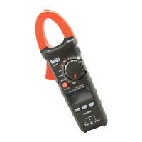
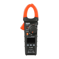
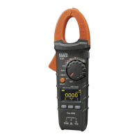
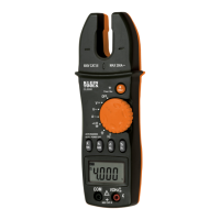
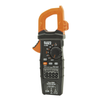
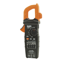
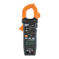
The Klein Tools CL320 is an automatically ranging True RMS digital clamp meter designed for a wide range of electrical measurements. It measures AC current via the clamp, AC/DC voltage, DC microamps, resistance, continuity, frequency, capacitance, and tests diodes using test leads. Additionally, it can measure temperature using a thermocouple probe.
Function Description:
The CL320 features a function selector switch (2) that allows you to choose between various measurement modes. To power on the meter, rotate this switch from the OFF setting to any desired measurement setting. To power off, return the switch to the OFF setting. By default, the meter includes an Auto Power-Off (APO) feature, which turns the device off after approximately 10 minutes of inactivity to conserve battery life. If the meter powers off during a measurement, you can press any button or cycle the function selector switch to OFF and then back ON to reactivate it. The APO function can be deactivated by pressing and holding the "SELECT" button (12) while powering on the meter; when deactivated, the Auto Power Off icon will not be visible on the display.
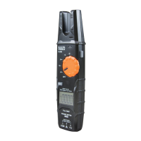
The meter is equipped with a "SEL/NCV" button (12) for Non-Contact Voltage (NCV) testing. Press and hold this button to enter NCV mode. The NCV icon and "EF" will appear on the display. When the sensing antenna (14) approaches a conductor with AC voltage (40V AC or greater), the red NCV light (13) will flash, audible beeps will sound, and dashes will appear on the display. The number of dashes and the frequency of the audible sound will increase as the antenna gets closer to the voltage source. Releasing the "SEL/NCV" button exits NCV testing mode.
A backlight button (6) is available to turn the display backlight ON or OFF. The backlight does not automatically turn off.
The CL320 operates in auto-ranging mode (AUTO) by default, which automatically selects the most appropriate measurement range. For manual range selection, press the "RANGE" button (7). Repeatedly pressing this button cycles through available ranges. To return to auto-ranging mode, press and hold the "RANGE" button (7) for more than two seconds.
The "MAX/MIN" button (8) tracks and displays the maximum, minimum, and the difference between maximum and minimum values during continuous sampling. Pressing it toggles between these values, and the display updates if new maximum or minimum values are detected. To exit this mode and return to normal measuring, press and hold the "MAX/MIN" button (8) for more than two seconds.
The "DATA HOLD" button (9) allows you to freeze the current measurement on the display. Pressing it again releases the hold and returns to live measurement.
Usage Features:
- Connecting Test Leads: Ensure test leads are firmly seated in the input jacks to avoid intermittent readings. The RED lead should be inserted into the VΩµA jack (5), and the BLACK lead into the COM jack (4).
- AC Current (Less than 400A): To measure AC current, press the clamp trigger (10) to open the clamp and place it around a single current-carrying wire. Ensure the clamp is fully closed with the trigger released, and the wire passes perpendicularly through the center of the clamp, aligned with the arrow markings (11). Rotate the function selector switch (2) to the 40/400 A setting. For measurements less than 40A, switch to the 4A setting for better resolution. Disconnect test leads when measuring with the clamp.
- AC/DC Voltage (Less than 600V): Rotate the function selector switch (2) to the V~ setting. The meter defaults to AC measurement. To measure DC voltage, press the "SELECT" button (12) to toggle between AC and DC modes. The AC or DC icon on the LCD indicates the selected mode. Apply test leads to the circuit. If a "-" appears, the leads are applied in reverse. Open test leads in voltage mode may show mV readings due to noise, which is normal; touching the leads together will show zero volts.
- Continuity: Rotate the function selector switch (2) to the Continuity/Resistance/Capacitance/Diode-Test setting. The meter defaults to continuity testing; ensure the continuity icon ())) is visible. Remove power from the circuit before testing. Connect test leads across the conductor or circuit. An audible signal and resistance value less than 10Ω indicate continuity; "OL" indicates an open circuit. Do not attempt to measure continuity on a live circuit.
- DC Microamps (Less than 200µA): Rotate the function selector switch (2) to the µA= setting. Remove power from the circuit and open the circuit at the measurement point. Connect test leads in series with the circuit, then apply power to take the measurement. Do not attempt to measure more than 200µA.
- Resistance Measurements: Rotate the function selector switch (2) to the Continuity/Resistance/Capacitance/Diode-Test setting. Press the "SELECT" button (12) once to enter Resistance testing mode (Ω icon will appear). Remove power from the circuit. Measure resistance by connecting test leads to the circuit. "O.L." indicates an open circuit or failed resistor. Do not attempt to measure resistance on a live circuit.
- Capacitance: Rotate the function selector switch (2) to the Continuity/Resistance/Capacitance/Diode-Test setting. Press the "SELECT" button (12) twice to enter Capacitance testing mode (capacitor icon will appear). The meter should read 0 nF with open test leads. Remove power from the circuit. Measure capacitance by connecting test leads across the capacitor.
- Diode Test: Rotate the function selector switch (2) to the Continuity/Resistance/Capacitance/Diode-Test setting. Press the "SELECT" button (12) three times to enter Diode testing mode (diode icon will appear). Touch test leads to the diode. A reading of 200-800mV indicates forward bias; "OL" indicates reverse bias or an open device. A shorted device will show approximately 0mV.
- Frequency / Duty-Cycle: Rotate the function selector switch (2) to the Frequency/Duty-Cycle Hz% setting. The meter defaults to Frequency testing. Press the "SELECT" button (12) once to enter Duty-Cycle testing mode (ensure Hz or % icon appears). Measure by connecting test leads across the circuit.
- Temperature: Insert the K-type thermocouple into the VΩµA (5) and COM (4) jacks, observing polarity. Rotate the function selector switch (2) to the Temperature °F°C setting. The meter defaults to Fahrenheit; press the "SELECT" button (12) once for Celsius. Make contact between the thermocouple tip and the object to be measured. Remove the thermocouple before switching to other measurement functions. The included thermocouple is suitable for temperatures below 446°F / 230°C; for higher temperatures, use an appropriate K-type thermocouple.
Maintenance Features:
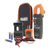
- Battery Replacement: When the battery indicator is displayed on the LCD, the batteries need to be replaced. Loosen the captive screw and remove the battery cover. Replace the 3 x AAA batteries, ensuring correct polarity. Securely fasten the battery cover. To avoid electric shock, disconnect all leads from any voltage source before removing the battery door. Do not operate the meter with the battery door removed.
- Cleaning: Ensure the meter is turned off. Wipe it with a clean, dry, lint-free cloth. Do not use abrasive cleaners or solvents.
- Storage: Remove the batteries if the meter will not be used for a prolonged period. Avoid exposing the meter to high temperatures or humidity. If stored in extreme conditions outside the specified limits, allow the meter to return to normal operating conditions before use.
- Disposal/Recycle: Do not dispose of the equipment and its accessories in household trash. Items must be disposed of properly according to local regulations. Refer to www.epa.gov or www.erecycle.org for additional information.