ENGLISH
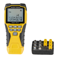
CABLE IDENTIFICATION - INSTALLED COAX CABLE
Testing Continuity
Testing Continuity-Installed
Testing Continuity-Term Coax
Testing Continuity- Installed Coax
1 2 3
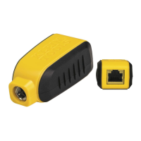
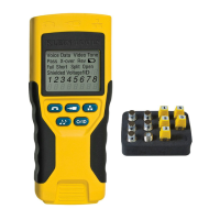
1. Insert a numbered CoaxMap remote into the F-connector port of each room that needs to be identified. Mark down pairs of
numbers and room names for later.
2. Take the VDV Scout™ Pro to the wiring closet or cable splitter (the source of the cable connection).
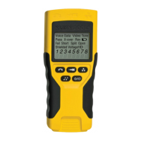
3. Connect an unknown cable to the video port on the top of the tester.
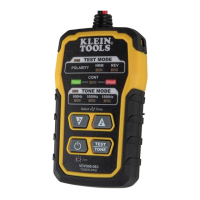
4. Press the ID button
on the keypad to begin the ID test on the ethernet cable. The LCD will read " Video ID#" where "#" is the
ID number of the CoaxMap remote connected to the other side of the cable. Compare this number to the number/room pair list
you made in step 1 and mark the cable with a piece of labeled tape.
5. Repeat steps 3 and 4 for each unknown cable until all have been labeled. You can use these labels to determine which rooms
should be connected to the cable splitter, or to troubleshoot intermittent connections in the future.
Note: Ethernet and coax cable can be identi ed simultaneously. When both cables are connected at the same time and the ID
button is pressed, "Video ID#" and "Data ID#" will alternate on the LCD screen.
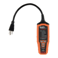
CABLE IDENTIFICATION - RJ45/RJ12 TONE TRACING
Testing Continuity
Testing Continuity-Installed
Testing Continuity-Term Coax
Testing Continuity- Installed Coax
1 2 3
1.
Connect a known working patch cable to the RJ45 port (if you are tracing an ethernet cable) or RJ12 port (if you are tracing a phone
cable) located at the top of the main tester body.
2. Connect the other end of the patch cable to the wall port at the satellite location of the cable under test (not at the wiring
closet).
3. Press the tone button
on the keypad to initialize the tone generation. Press it repeatedly to change the tone cadence from a
steady low or high tone to a warbling slow or fast tone.
4. Press the data button
or the phone button
repeatedly to select the output port of the tone and the pins the tone will be
placed on.
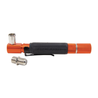
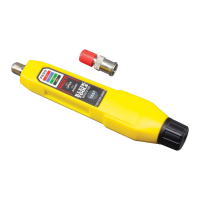
5. Take the analog tone probe to the wiring closet or router (the source of the internet connection). Activate the tone probe (see
tone probe instruction manual for details).
6. Place the tone probe near each cable entering the wiring closet. The tone will be loudest at the cable that the VDV Scout
TM
Pro
is connected to. Mark the cable with a label.
7. Repeat steps 2-6 for each room that has installed cable.
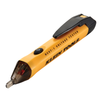
CABLE IDENTIFICATION - COAX TRACING
Testing Continuity
Testing Continuity-Installed
Testing Continuity-Term Coax
Testing Continuity- Installed Coax
1 2 3