Do you have a question about the Klein Tools VDV526-200 and is the answer not in the manual?
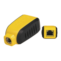
Describes RJ45 shielded jacks on the main tester and remote.
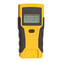
Details the function of the Test, Tone, and Power/Backlight buttons.
Indicates tone transmission and conductor wires being toned.
Indicates a properly wired data or crossover cable.
Indicates a correctly wired crossover pattern.
Indicates a correctly assembled shield contact.
Alerts to detected voltage, preventing testing.
Indicates incorrect wiring to cabling standards.
Indicates a short on conductor wires.
Indicates designated wire pairs are not terminated correctly.
Indicates an unterminated conductor wire.
Signals low battery, potentially affecting results.
Shows pin mapping from the tester end.
Shows pin mapping to the remote end with dashed lines for shorts.
Controls unit power and backlight.
Initiates cable tests, default loop mode.
Transmits analog tones on conductor wires.
Example of correctly wired UTP cable test result.
Example of a cable with split pairs.
Example of a cable with short and open faults.
Example of a cable wired incorrectly according to T568A standard.
Instructions for tracing tones on uninstalled cables.
Instructions for tracing tones on installed cables.
| Test type | Continuity testing |
|---|---|
| Cable type | Cat7, Cat6/6A, Cat5E, Cat3 |
| Display type | LCD |
| Product type | Twisted pair cable tester |
| Product color | Black, Yellow |
| Built-in display | Yes |
| Supported connectors | RJ-45 |
| Battery type | AAA |
| Battery technology | Alkaline |
| Number of batteries supported | 2 |
| Depth | 130 mm |
|---|---|
| Width | 64 mm |
| Height | 25 mm |
| Weight | 122 g |