Do you have a question about the Klimaire KSWM009-H113 and is the answer not in the manual?
Instructions to prevent injury and property damage during operation and handling.
Warnings and cautions related to the installation of the unit.
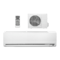
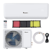
Functions and operations specific to the indoor unit.
Functions and operations specific to the outdoor unit.
Physical dimensions of the indoor unit for various models.
Physical dimensions of the outdoor unit for various models.
Diagram illustrating the refrigerant flow during cooling operation.
Diagram illustrating the refrigerant flow during heat pump operation.
Chart showing operational temperature ranges for cooling.
Chart showing operational temperature ranges for heating.
Wiring diagram for KSWM009-C113 indoor and outdoor units.
Wiring diagram for KSWM009-H113 indoor and outdoor units.
Wiring diagram for KSWM012-C113 indoor and outdoor units.
Wiring diagram for KSWM012-H113 indoor and outdoor units.
Wiring diagram for KSWM018-C213 indoor and outdoor units.
Wiring diagrams for KSWM018-H213 and KSWM024-H213 units.
Torque specifications for wrench tightening during installation.
Guidelines for selecting power cords based on amperage.
Specifications for refrigerant pipe length and elevation differences.
Procedure for purging air from the refrigeration system.
Procedure for pumping down refrigerant during re-installation.
Procedure for re-purging air during re-installation.
Procedure to balance refrigerant using 2-way and 3-way valves.
Procedure for vacuum evacuation of the refrigeration system.
Procedure for charging refrigerant into the system.
Operating parameters and conditions for electronic controls.
Explanation of symbols used in electronic functions.
Overview of various electronic functions and features.
Details on compressor and system protection mechanisms.
Description of the fan-only operating mode.
Details on cooling mode operations and controls.
Description of the dehumidifying operating mode.
Details on heating mode operations and controls.
Function to prevent cold air during heating startup.
Automatic fan speed control during heating.
Protection against high evaporator temperature in heating.
Operation and conditions for defrosting mode.
Criteria for the termination of defrosting mode.
Sequence of actions during defrosting mode.
Automatic selection of operating modes based on temperature.
Function to force the unit into cooling operation.
Energy-saving sleep mode for cooling, heating, or auto.
Details on the auto function within sleep mode.
Automatic restart after power interruption.
High-speed operation mode for rapid temperature achievement.
Explanation of indicators on the display board for different models.
Table of failure phenomena and corresponding indicator status.
Flowcharts for diagnosing specific operational issues for different models.
Diagnosis for frequent resetting issues.
Troubleshooting for uncontrolled indoor fan speed.
Troubleshooting steps for temperature sensor errors.
Diagnosis for compressor over current protection faults.
Troubleshooting for EEROM errors.
Troubleshooting for outdoor unit protection faults.
Troubleshooting for indoor unit communication failures.
| Cooling Capacity | 9000 BTU/h |
|---|---|
| Energy Efficiency Ratio (EER) | 11.0 |
| Refrigerant | R410A |
| Voltage | 115 V |
| Power Consumption (Cooling) | 820 W |
| Power Consumption (Heating) | 780 W |
| Air Flow (High) | 320 CFM |
| Power Supply | 1 Phase, 60 Hz |
| Operating Temperature (Cooling) | 62°F to 90°F |
| Operating Temperature (Heating) | 32°F - 86°F |