Do you have a question about the Klimaire KSWM009-C113 and is the answer not in the manual?
General safety instructions to prevent injury and property damage.
Warnings regarding electrical hazards, improper installation, and operational risks.
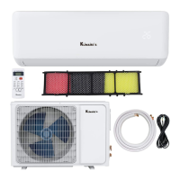
Describes the functions and operations of the indoor unit.
Describes the functions and operations of the outdoor unit.
Specifies the physical dimensions of the indoor unit for various models.
Specifies the physical dimensions of the outdoor unit for various models.
Diagram illustrating the refrigerant cycle during cooling operation.
Diagram illustrating the refrigerant cycle during heat pump operation.
Specifies the temperature limits for effective cooling operation.
Specifies the temperature limits for effective heating operation.
Wiring diagram for the KSWM009-C113 model.
Wiring diagram for the KSWM012-C113 model.
Wiring diagram for the KSWM012-H113 model.
Wiring diagrams for KSWM018-H213 and KSWM024-H213 models.
Covers wrench torque, cable connection, pipe length, and elevation.
Procedure for removing air from the refrigeration piping and indoor unit.
Procedure for creating a vacuum in the refrigeration system.
Procedure for charging the system with the correct amount of refrigerant.
Specifies the operating environment for the electronic control system.
Defines the meaning of various symbols and sensor designations used.
Lists the various functions and features of the air conditioner.
Details various protection mechanisms to prevent damage and ensure safe operation.
Describes the operation when only the fan is active.
Details the operation and controls during cooling mode.
Describes the operation of the dehumidifying mode.
Details the operation and controls during heating mode.
Covers anti-cold wind and auto fan control in heating mode.
Details high-temperature protection for the indoor evaporator during heating.
Explains the defrosting mode and its conditions.
Specifies the conditions that end the defrost cycle.
Illustrates the sequence of actions for the defrost cycle.
Describes how the unit automatically selects operating modes.
Details the forced cooling operation.
Explains the sleep or economic mode for energy saving.
Describes automatic temperature adjustments in sleep mode.
Explains the auto restart feature after power interruption.
Details the turbo mode for rapid cooling.
Explains the indicators on the display board for different operating modes.
Lists failure phenomena and corresponding indicator lamp status for troubleshooting.
Provides a diagnostic chart for troubleshooting when the unit is not operating.
Troubleshooting steps for intermittent resetting of the unit.
Troubleshooting steps for issues with indoor fan speed control.
Troubleshooting steps for temperature sensor errors.
Troubleshooting for repeated compressor over-current protection.
Troubleshooting for EEPROM errors, indicating potential indoor PCB issues.
Troubleshooting steps for outdoor unit protection faults.
Troubleshooting steps for indoor unit communication errors.
| Cooling Capacity | 9, 000 BTU/h |
|---|---|
| Energy Efficiency Ratio (EER) | 11.0 |
| Refrigerant | R410A |
| Weight (Indoor Unit) | 17.6 lbs |
| Voltage | 115V |
| Seasonal Energy Efficiency Ratio (SEER) | 19.0 |
| Noise Level (Outdoor Unit) | 52 dB |
| Heating Seasonal Performance Factor (HSPF) | 10.0 |
| Operating Temperature (Cooling) | 64-90°F |
| Heating Capacity | 9, 000 BTU/h |
| Operating Temperature (Heating) | 41-86°F |