Page 12 of 28
Assembly Instructions
WARNING
• Turn the power Switch of the tool off and unplug the tool from its electrical outlet before
performing any procedure.
• Before assembling and using the Drill Press, secure the Base to a supporting structure.
• Verify that the intended installation surface has no hidden utility lines before drilling or driving
screws.
• Bolt the Base to a flat, level, solid floor location capable of supporting the weight of the Drill
Press and any workpieces.
COLUMN ASSEMBLY TO BASE
1. Attach the Column Support (2) to the Base (1) using the four M10x35 Bolts (5), four Spring
Washers (4) and four Flat Washers (3).
2. Tighten the Bolts firmly
3. Insert the Column (7) into the Support and firmly secure this assembly in place with the Set
Screws (6).
Note: It may be necessary to back the Set Screws out beforehand, as they may protrude into the
Support tube, preventing the Column from sliding fully into the Column Support.
TABLE TO COLUMN
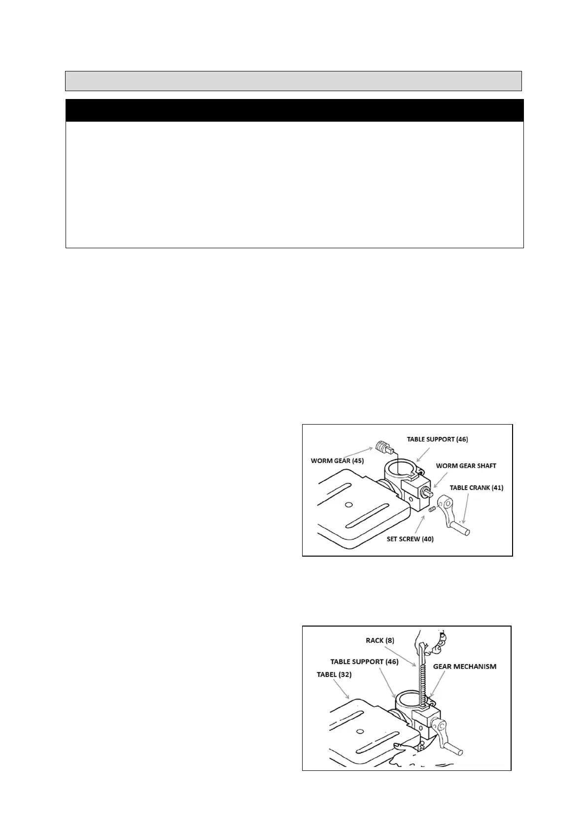
1. Lubricate the Worm Gear (45) teeth with light
grease and insert the Gear shaft-first into the
Table Support (46). Extend the shaft as far as
possible through the opening in the side of the
Support. See Figure A.
2. Insert the Table Crank (41) onto the protruding
Worm Gear shaft. Align the Table Crank′s Set
Screw (40) with the flat portion of the Worm
Gear shaft. Make sure the Worm Gear shaft is
inserted as far as possible into the Crank, then
tighten the Set Screw. See Figure A.
3. Use the Socket Head Cap Screw (44) to attach the Table Crank Handle (43) to the Table Crank.
Use a hex key (not supplied) to securely tighten the Crank Handle.
4. Loosen the Set Screw (16) in the Collar (17) and remove the Collar and Rack (8) from the Column.
The Rack is stowed in this position only for transit purposes.
5. With the long smooth end of the Rack upper
most, slide the Rack down through the notch in
the opening in the Table Support, as shown in
Figure B. Engage the Rack into the Gear
Mechanism located on the inside of the Table
Support.
Figure A
Figure B
 Loading...