Page 13 of 28
6. While holding the Rack and the Table Support as assembled, slide both down onto the Column.
Slide the Rack down until the bottom of the Rack is positioned against the Column Support.
7. Replace the Collar onto the Column with its beveled side down, ensuring that the top end of the
Rack is engaged in the groove formed between the Collar and the Column.
IMPORTANT: Make sure the Rack is not pinched and there is a working clearance between the
Rack and Collar.
8. Tighten the Collar Set Screw.
Note: For the Rack to move easily when the Table is rotated around on the Column, the Collar
must sit evenly on the Column and fit loosely over the top of the Rack. Only tighten the Collar Set
Screw enough to keep the Collar in place on the Column. Overtightening the Set Screw may
damage the Collar.
9. Check the Collar for proper adjustment. The Rack should move freely when the Table is rotated
the full 360º around the Column.
10. Screw the Table Lock Handle (36) into the Table Support but do not tighten it all the way. Once
this is done, turn the Crank, testing to ensure that the Table Support easily travels up and down
the full length of the Rack without binding, and that the assembly and the Rack rotate freely all the
way around the Column without binding.
IF THE TABLE SUPPORT IS TOO TIGHT:
• Slightly loosen the Table Lock Handle and loosen the Collar Set Screw.
• Adjust the Collar slightly to provide a greater working clearance between the Rack and the
Collar
• Tighten the Collar Set Screw, and test the Table Support′s movement again.
HEAD ASSEMBLY TO COLUMN
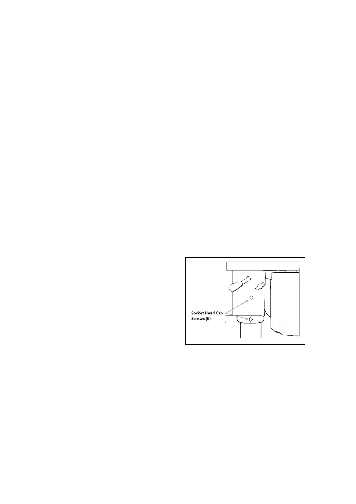
1. Before installing the Head Assembly, it may be
necessary to back the four Socket Head Cap
Screws (6) out slightly to ensure they do not
protrude internally, as this would prevent the
Head Assembly from sliding fully into position.
as shown in Figure C
2. With assistance, raise the Head assembly and
locate it on top of the Column.
3. Align the Head with the Base, and firmly
secure it with the Set Screws.
4. Screw the three Spindle Feed Handle Bars (9)
firmly into the Spindle Feed Hub (10).
ATTACHING THE PULLEY COVER HANDLE
1. Slide the Pulley Cover Handle (118) into the hole in the front of the Pulley Cover.
2. Put the Cross-Shape Screw (28) through the Flat Washer (27) and twist it into the Handle from
the inside of the Pulley Cover.
INSTALLING THE CUTTING OIL SYSTEM
1. Use four Socket Head Cap Screws (120) and four Rubber Pads (88) to attach the two Oil Bottle
Clips (121) to the tapped holes in the left side of the Head.
2. Thread the Oil Pipe (76) into the bottom of one of the Oil Bottles (56), screw an Oil Bottle Cap
(53) onto the Bottle and snap the Bottle into the Oil Bottle Clips.
Figure C
 Loading...