Page 14 of 28
INSTALLING THE BELTS
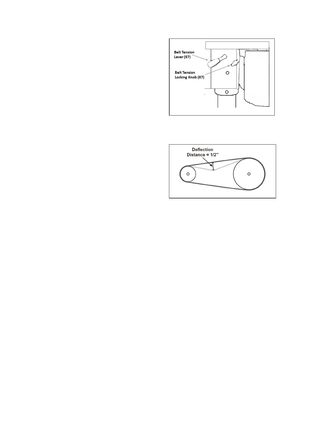
1. Undo the Belt Tension Locking Knobs (87) on
both sides of the Head. Turn the Belt Tension
Lever (97) clockwise to bring the Motor Pulley
(109) towards the Spindle Pulley (69), allowing the
Belts to be easily slipped over the Pulleys. as
shown in Figure D
2. Lubricate the Idler Pivot Shaft (111) and Idler
Pulley (112) with light grease, and install the Pivot
Shaft in its mounting between the Motor Pulley
and Spindle Pulley.
3. Consult the chart inside the Pulley Cover ( Figure G on page 16), and install the Belts (70, 113)
in the positions corresponding to the required spindle/drill speed.
4. Turn the Belt Tension Lever counterclockwise so
that tension is applied to the belts. as shown in
Figure E
IMPORTANT: Tension is correct when the belts
deflect by approximately 1/2″ at their centers of
run when using reasonable thumb pressure.
5. Use the Belt Tension Locking Knobs to lock the
Motor Pulley in this position.
INSTALLING THE CHUCK
1. Loosen the Table Lock Handle (36) and slide the Table up the Column to within 6″ of the Arbor
(58). Tighten the Lock Handle.
2. Thoroughly clean the Arbor and the tapered hole in the Chuck (57) of all dirt, grease, oil, and
protective coatings.
3. Slide the Chuck onto the Arbor.
4. Examine the Chuck from all sides to make sure that it is straight.
5. Open the jaws of the Chuck to their maximum, using the supplied Chuck Key.
6. Put a piece of scrap wood on the table to protect the Chuck nose.
7. Using the Spindle Feed Handles, lower the Spindle and press the Chuck nose hard against the
scrap wood on the table until the Chuck is forced into a solid fit. The Chuck is pressure fitted.
Figure D
Figure E
 Loading...