Page 16 of 28
CHANGING DRILL SPEED
1. Open the Pulley Cover.
2. Loosen the Belt Tension Lock Knobs on both sides of the Head and turn the Belt Tension Lever
clockwise. This will bring the Motor Pulley towards the Spindle Pulley, removing all tension from
the drive Belts.
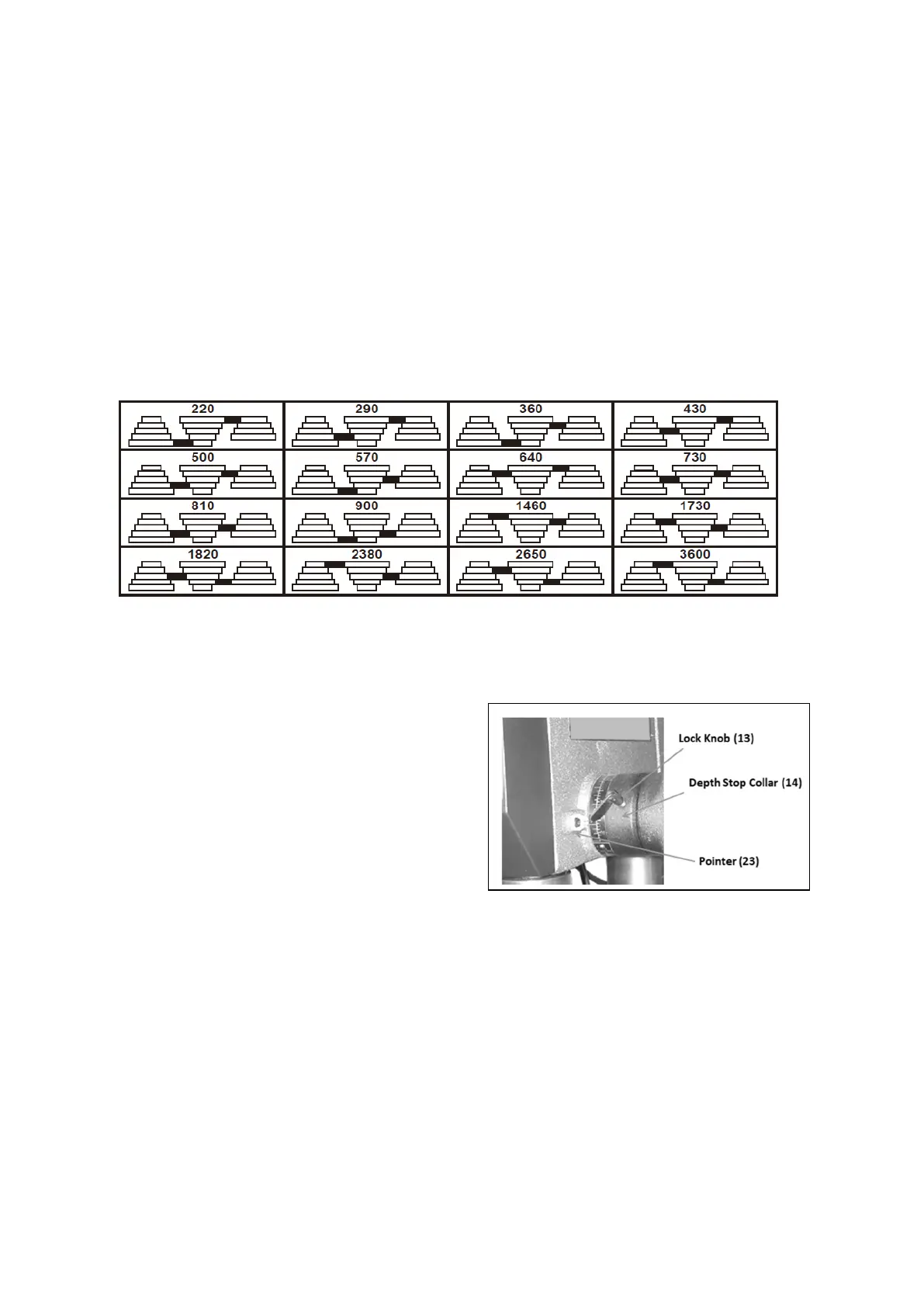
3. Consult Figure G (or the chart inside the Pulley Cover) and install the Belts on the Pulleys in the
positions that correspond to the required Spindle/Drill speed.
4. When the Belts have been correctly positioned, tighten them by turning the Belt Tension Lever
counterclockwise. The tension is correct when the belts deflect by approximately 1/2″ at their
centers of run when using reasonable thumb pressure. (See Figure D on page 14.) Lock this
position in with the two Belt Tension Lock Knobs. as shown in Figure D
Note: If a belt is too long to be properly tensioned, it must be replaced.
SETTING THE DRILLING DEPTH
Located around the Spindle Feed Shaft is a Depth Stop Collar (14) carrying a graduated scale. The
Collar will turn around the Shaft, and can be locked in place by the Lock Knob (13).
1. With the power to the Drill Press switched OFF,
use the Spindle Feed Handles to lower the drill
until the bit contacts the workpieces and hold it
in that position.
2. Loosen the Lock Knob and turn the Depth Stop
Collar so that the measurement for the required
hole depth is aligned with the Pointer (23).
3. Tighten the Lock Knob to lock the Collar in this
position. as shown in Figure H
USING THE CUTTING OIL DRIP SYSTEM
1. Remove the upper Oil Bottle from the Oil Bottle Clips and unscrew the Cap.
2. Make sure that the Oil Pipe valve is closed. Fill the Bottle with your lubricant of choice.
3. Screw the Cap onto the Bottle and snap the Bottle back into the Clips.
4. Open the Oil Pipe valve and adjust the Pipe so the oil drips onto the cutting area.
5. The used oil will collect in the Oil Bottle that is attached to the underside of the Work Table.
·Dispose of the used oil in accordance with local regulations.
Figure G
Figure H
 Loading...