• the left figure : Σcos φ = 0.98 inductive (choke symbol displayed). Furthermore, active three phase
power is being negative, therefore the leading “minus”-sign ( and the symbol displayed )
• the middle figure : Σtan φ = 0.20 inductive. Active three phase power is positive.
• the right figure : Σφ = 8 degrees inductive. Active three phase power is positive.
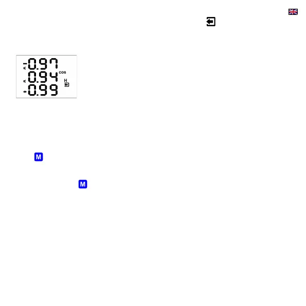
On the figure on the left, there is phase cos φ values example :
• cos φ1 = 0.97 inductive. L1-phase active power is currently negative (because
of leading “minus”-sign)
• cos φ2 = 0.94 inductive ( L2-phase active power currently positive )
• cos φ3 = 0.99 capacitive ( L3-phase active power currently positive )
2.6 THDs and Harmonic Components
You can check actual values of both voltage and current THDs and harmonic components in appropriate rows (see the
Measured Data Navigation Chart ).
When you scroll to one of this rows, THD values of all measured phases are displayed as default. Symbols THD - V - LN or
THD - A indicate phase voltage or current THD values, respectively.
With the key you can switch to harmonic components. The symbol H appears, indicating harmonic components (of
voltage or current). Symbol % means that the values are expressed in percent of fundamental harmonic component. Order of
harmonics just displayed flashes periodically in the display middle line – for example, string H03 means 3
rd
harmonics.
By repetitive pressing of the key you can check other harmonics. Although the instrument evaluates all of the harmonic
components up to 40
th
order internally, only odd components to 25
th
order can be viewed of its display (full spectrum od the
harmonics is available via communication interface only).
2.7 Electricity Meter
Electricity meter comprises three-phase energy data and maximum tree-phase active power demand value. The values are
situated in particular row.
Depending on the parameter 08 setup, two electricity meter display modes can be chosen :
• “4E+MD” mode (default)
• “8E” mode