CTE-5202 Electronic Room Thermostat with LCD Display 2 Installation and Operation Guide
Operation
Change Setpoint
Tochangethesetpoint:
1. PushtheSetpointbuon(oreitherUp/Down
buon)todisplaythecurrentvalue.
NOTE: Sequences2and3havetwosetpoints
indicatedby“snowake/cool”and“re/
heat”icons.WhentheCoolingsetpointis
showing,pushingtheSetpointbuonwill
displaytheHeatingsetpoint.
2. UsetheUp/Downbuonstochangethevalue.
3. PresstheSetpointbuonagain,andthethermo-
statwillcontrolatthenewsetpoint.(Alternately,
aerabout30secondsofnoactivity,thedisplay
revertsbacktodisplayingroomtemperature.)
Change Configuration
Press and hold both the Up and Down arrows
buons for about ten seconds
untilthedisplaystarts
ashing“LIMITS.”
NOTE: Whenamenuisashing(LIMITS,
ADVANCE,SYSTEM,orEXIT),
pressingUporDowndisplaysthenext
menuitemandpressingSetpointselects
thatmenu.WhenamenuisNOTashing
(e.g.,DEAD BD),pressingUporDown
changesthevalueandpressingSetpoint
displaysthenextmenuitem.
Tochangeanyofthelimits (output span) when
“LIMITS”isashing,presstheSetpointbuon
untilthedesiredlimit(AO1 MIN,AO1 MAX,AO1
AUX
,AO2 MIN,orAO2 MAX)isashingonthe
screen.(Limits are adjustable from 0 to 12 VDC, with
MIN = 0, MAX = 12, and AUX = 0 as defaults.
)Usethe
UpandDownbuonstochangethedesiredvalues.
(If no Auxiliary Flow is desired, set AO1 AUX to 0.)
Tochangeanyofthesystem or advanced features,
presstheUporDownbuonuntilthedesired(ash-
ing)ADVANCEorSYSTEMmenuappearsand
thenpresstheSetpointbuon.
3. Withthehexscrewstowardtheoor,fastenthe
backplatetotheoutlet/handyboxwiththesup-
pliedscrews.(Thebackplatemountsdirectlyon
vertical2x4inchboxes,butrequiresanHMO-
1161/HMO-1161Wwallplateforhorizontal2x4,
4x4,orotherboxes.)
4. Connectthewirestotheterminalblock:
• “Heating”output(REE-50xxreheatrelay
modulesandheatingvalves)toAO2and
T
(Common)
• “Cooling”
output(VAVdampersandcooling
valves)toAO1and
T
(Common)*
• Changeover
(temperature)sensor(TypeIII,
10Kohmthermistor)and/orstandby/unoccu-
piedsetbackcontacttoAI1and
T
(Common).
(SeeExternal Input (AI1) on page 4.)
• 24 VAC
transformer’sneutralleadto
T
(Com-
mon)andphaseleadto~.Alternately,14–35
VDCcanbeusedwith+ connected to ~ and
– connected to
T
(Common).
*NOTE: For additional wiring details, cross-
references sample applications, and
examples of AO1 being used for heating
instead of or in addition to cooling, see the
CTE-5202 Applications Guide.
5.
Placethetopofthethermostatoverthetopof
themountingbaseandswingitdownoverthe
hexscrewbrackets.Becarefulnottopinchthe
wiring.
6.
Backthehexscrewsoutofthebackplatebrackets
(counterclockwise) untiltheyengagethether-
mostatandholditinplace.
NOTE: For examples of applications, including
replacing a CTE-510x with the CTE-5202,
see the CSP-5001/5002 Applications Guide.
~
T
T
AO2
“Heating” Output
AO1
“Cooling” Output
Common
Common
Power (AC Phase or DC +)
Input
AI1
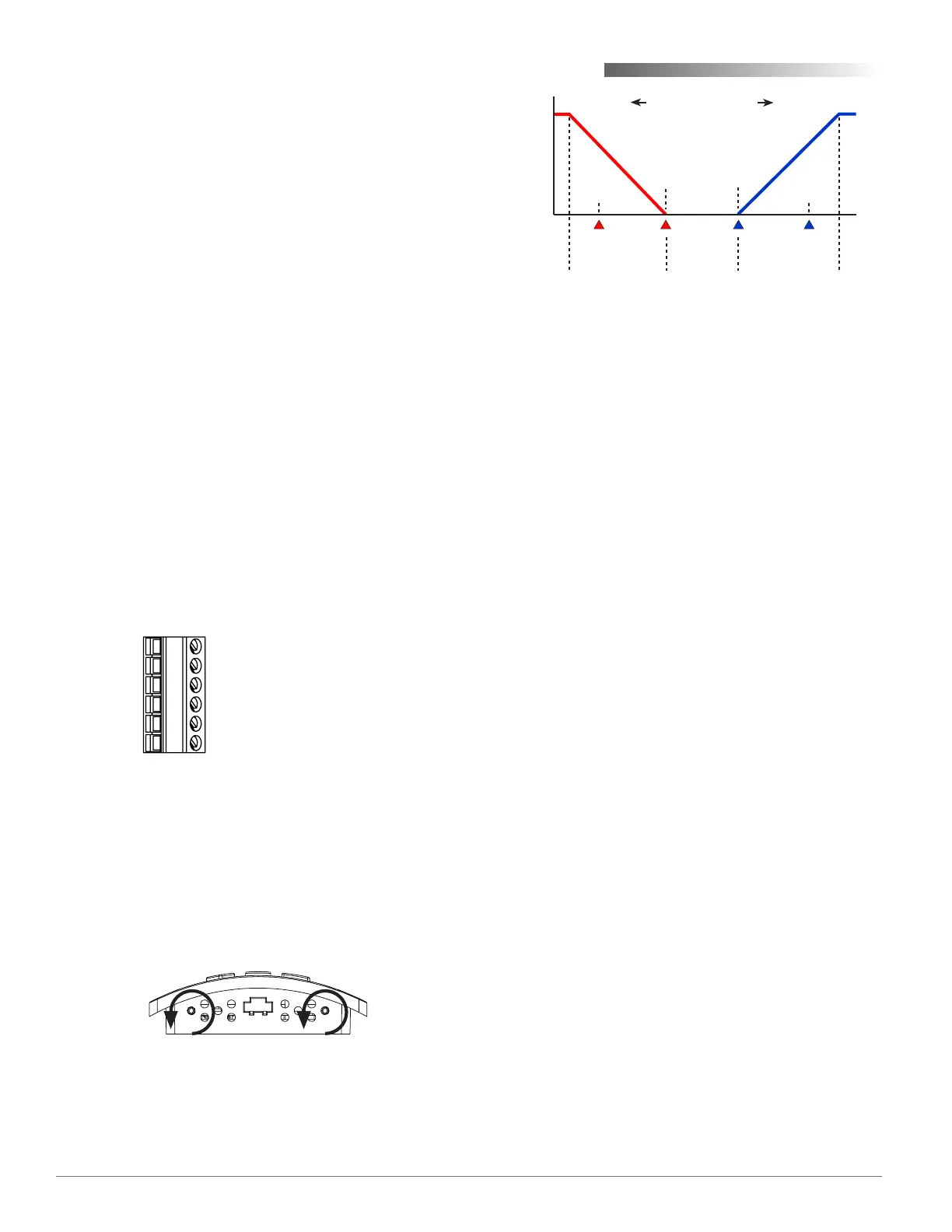
(Colder Room Temperature Warmer)
Cooling
Setpoint
Heating
Setpoint
Proportional
Band
Proportional
Band
Deadband
(Cooling)
Setback
(Heating)
Setback
Max.
Limit
Min.
Limit
Output
Span
 Loading...