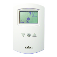
CTE-5202 Electronic Room Thermostat with LCD Display 1 Installation and Operation Guide
1. Ifthethermostatislockedonthebackplate,turn
thetwohexscrews(inthetwo outermost holes)
inthebackplateCLOCKWISEuntilthey(just)
clearthecover.Swingthethermostatupand
awayfromthebackplatetoremoveit.
Installation and Operation Guide
Electronic Room Thermostat with LCD Display
CTE-5202
Installation
Rough-in Preparation
For optimum temperature sensor performance, the
thermostat must be mounted on an interior wall
and away from heat sources, sunlight, windows,
air vents, and air circulation obstructions (e.g.,
curtains, furniture).
Ifreplacinganexistingthermostat,labelwiresas
neededforreferencewhenremovingtheexisting
thermostat.
Completerough-inwiringateachlocationpriorto
thermostatinstallation.Cableinsulationmustmeet
localbuildingcodes.
Installation 1
Rough-in Preparation 1
Mounting and Wiring 1
Operation 2
Change Setpoint 2
Change Configuration 2
External Input (AI1) 4
Maintenance 4
Accessories 4
Additional Resources 4
Important Notices 4
CAUTION
To prevent damage to the board, do not insert
a screwdriver into any holes other than the two
outermost holes. To prevent mounting screw heads
from touching the circuit board in the thermostat, use
only the mounting screws supplied by KMC Controls.
Using other screws may damage the thermostat. Do
not turn screws in farther than necessary to remove
the cover.
2. Routethecablethroughthebackplate.
~
T
T
AI1
AO1
AO2
SET
POINT
A
A B C D E
3.25in. 5.16in. 0.88in. 3.25in. 0.15in.diameter
83mm 116mm 22mm 83mm 3.81mmdiameter
B
C
D
E
Mounting and Wiring
ThethermostatmustNOTbe:
• Mountedonanexteriorwall.
• Mountedonornearalargethermalmass(e.g.,
concreteblockwall).
• Blockedfromnormalaircirculationbyobstruc-
tions.
•
Exposedtoheatsources(e.g.,lights,computers,
copiers,orcoeemakers)ortosunlight(atany
timeoftheday).
• Exposedtodrasfromwindows,diusers,or
returns.
•
Exposedtoairowthroughtheconduit(from
leaksinplenumducts)—putplumber’spuyor
similarmaterialinsidetheconduittoblockair
ow.
NOTE: For specications and other information,
see the CTE-5202 Data Sheet.
NOTE: For detailed applications, cross-references,
accessories, and other information, see the
CTE-5202 Applications Guide.