19
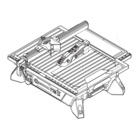
INSTALLING THE CUTTING HEAD ASSEMBLY
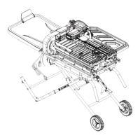
TO TABLE FRAME (FIG. 8) - BAG W
NOTE: The cutting head assembly and table frame
are heavy and it is recommended to be transported
with the help of 2 people, to safely move it.
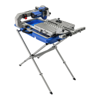
● Place the table frame (C) and cutting head
assembly (A) on a at, secure surface.
● Align the holes in the cutting head
assembly (A) with the holes on the table
frame (C).
NOTE: Make sure that two location pins (1)
are fully engaged with two holes (2) in the
cutting head assembly (A).
● Thread two bolts (pp) through two spring
washers (qq) and two at washers (rr) into
the holes under the table frame and into the
cutting head assembly.
● Tighten the bolts using the provided 10 mm
hex wrench (Gg).
● On the cutting head assembly, pull out the
hold-down latch (SS) and grasp the motor
handle (KK) to raise up the cutting head.
● Release the hold-down latch (SS) to lock
into place and tighten the cutting head lock
knob (MM) to secure the cutting head.
NOTE: Make sure the cutting head locking
knob (MM
)
is fully engaged with the channel
before locking.
● Pull out the arm folding lock knob (FF) and
grasp the motor handle (KK) to raise the
cutting head assembly up. Push in the arm
folding lock knob (FF) and tighten it.
8
SS
MM
C
A
pp
qq
rr
1
Bottom view
2
FF
KK
 Loading...