25
● Disconnect the saw from the power source.
● Move the sliding table to the front of the saw.
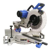
● Loosen the cutting head lock knob (MM) and
pull out the hold-down latch (SS) to raise the
cutting head to its upmost position. Release
the hold-down latch (SS) and tighten the
cutting head lock knob (MM). (Fig. 15)
● Loosen the wheel guard lock knob (YY) to
open the upper wheel guard (ZZ).
● Place the wheel wrench (OO) on the arbor
nut (XX).
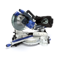
● Press the arbor lock button (Aa), holding
it in rmly while turning the wheel wrench
counterclockwise to loosen. (Fig. 16)
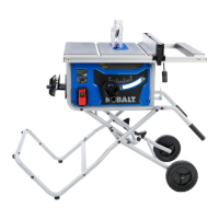
● Remove the arbor nut (XX) and outer
ange (1). (Fig. 17)
NOTICE: Do not remove the inner ange (2).
● Place the 10 in. wheel (J) onto arbor. Make
sure that the wheel’s rotation arrow points in
the same direction as the rotation arrow on
the front of wheel guard.
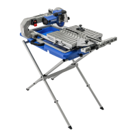
NOTICE: The tile saw is equipped with two
water nozzles (WW) to wet the wheel during
operation. Make sure holes in nozzles face
the wheel and that wheel is positioned
between the two nozzles.
● Place outer ange (1) onto the arbor. The
ats on the outer ange align with the ats
on the arbor. Install with the cupped side of
the outer ange facing the tile saw wheel.
INSTALLING THE CUTTING WHEEL
(FIG.15, 16, 17)
WARNING
● DO NOT use cutting wheels rated less than
the no load speed of this tool. Failure to heed
this warning could result in personal injury.
DO NOT use a wheel with cracks, gaps, or
teeth.
● A 10 in. tile saw wheel is the maximum wheel
capacity of the saw. NEVER use a wheel
that is too thick. Larger wheels will come
in contact with the anti-splash guard, while
thicker wheels will prevent the wheel bolt
from securing the wheel on the arbor. Either
of these situations could result in serious
accidents and can cause serious personal
injury.
15
OO
XX
YY
ZZ
MM
SS
16
Aa
17
XX
1J
2
WW
Do not remove
inner ange
 Loading...