7
ASSEMBLY INSTRUCTIONS
gnment
achieved.
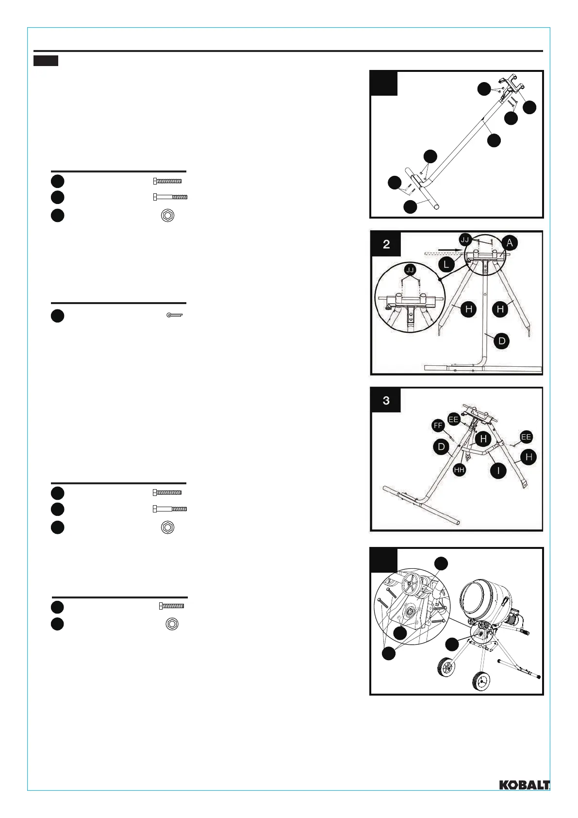
1. Attach bottom casting (A) to rear leg (D) using two M8 × 45
bolts (EE) and two M8 nuts (HH).
Attach rear leg cross member (E) to rear leg (D) using two
M8 × 60 bolts (FF) and two M8 nuts (HH).
DO NOT COMPLETELY TIGHTEN.
DO NOT COMPLETELY TIGHTEN.
2. Slide pivot pin (L) through bottom casting (A) and front
legs (H). Insert cotter pins (JJ) into pivot pin (L).
3. Assemble lower frame support (I) to front legs (H)
using two M8 x 45 mm bolts (EE) and M8 nuts (HH).
Assemble lower frame support (I) to rear leg (D) using
M8 x 60 mm bolt (FF) and M8 nut (HH).
Be sure to secure cotter pins (JJ) properly into pivot pin (L)
before moving onto next step.
Note Fasteners should only be tightened after final ali
HARDWARE USED
2
M8 × 45mm Bolt
EE
2
M8 × 60mm Bolt
FF
4
M8 Nut
HH
HARDWARE USED
2
M8 × 45mm Bolt
EE
1
M8 × 60mm Bolt
FF
3
M8 Nut
HH
HARDWARE USED
2
Cotter Pin
JJ
4.
Assemble front cover (K) to front legs (H) using four
M8 × 40 mm bolts (DD) and M8 nuts (HH).
HARDWARE USED
4
M8 × 40mm Bolt
DD
4
M8 Nut
HH
A
EE
HH
FF
HH
E
D
1
4
K
K
HH
DD
kobalttools.com
 Loading...