F3
F2
F4
RE1
RE2
RE3
RE4
RE5
RE6
RE7
RE8
42
42
42
42
42
42
41
41
41
41
500mA
F5
500mA
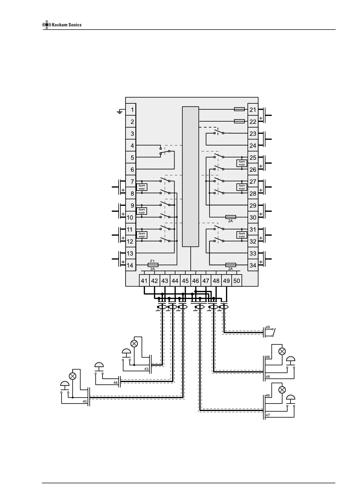
General external wiring diagram for Signal Controller TLG 2000
Shows all possible electrical connections.
For example of more specic applications, see page 12 to 15.
Mains for MORSE LIGHT
115...230V AC
or 24V DC
Mains for TYFON
115...230V AC
or 24V DC
Output to
Aft TYFON
Output to
Fore TYFON
distance between
whistles <= 100m***
Output to
Fore TYFON
distance between
whistles > 100m***
24V DC power supply for
Signal Controller TLG2000
GEA active**
Output to GONG
Output to BELL
Mains for BELL & GONG
115...230V AC
or 24V DC
Output to MORSE LIGHT
TYFON active*
PA interrupt for GEA
(yard’s supply)
External
MORSE LIGHT
switch type
TL-70
External
TYFON
switch type
TL-80 or
TL-85
External
start button
for automatic
TYFON type
TL-80 or
TL-85
Shielded cable
Shielded cable
Shielded cable
Signal Controller
TLG2000
or
Notes.
* This potential free relay output is used in conjunction with
external Sound Signal Surveillance System type S90.
The relay output will change state when the Control Unit is
activating a TYFON. Max load 230V AC/800mA...30V DC/
800mA
** A potential free relay output that will change state when an
GEA (General Emergency) alarm is activated on the Control Unit.
Max load 230V AC/1.6A...30V DC/1.6A
*** See page 2 and 3 for explanation
Shielded cable
Shielded cable
Yes
No
Common
Control Unit
Abandon ship
(In this example this
LED is connected to the
dimmer)
General Emergency
Alarm (GEA)
(In this example this
LED is connected to the
dimmer)
TL-80 versions shows TL-85 types.
See page 16 for dierent types of push buttons.
All cables to be shielded and shield connected to ships ground.
For details of switch and LED terminal markings, see page 10.
Page 11 of 20
TLG2000 Signal Controller Instruction Manual
IMPORTANT! See page 8 for
correct supply connection.
 Loading...