F3
F2
F4
RE1
RE2
RE3
RE4
RE5
RE6
RE7
RE8
42
42
42
42
42
41
42
41
jumper
500mA
F5
500mA
GEA active*
External
MORSE LIGHT
switch type
TL-70
External
TYFON
switch type
TL-80 or
TL-85
External
start button
for automatic
TYFON type
TL-80 or
TL-85
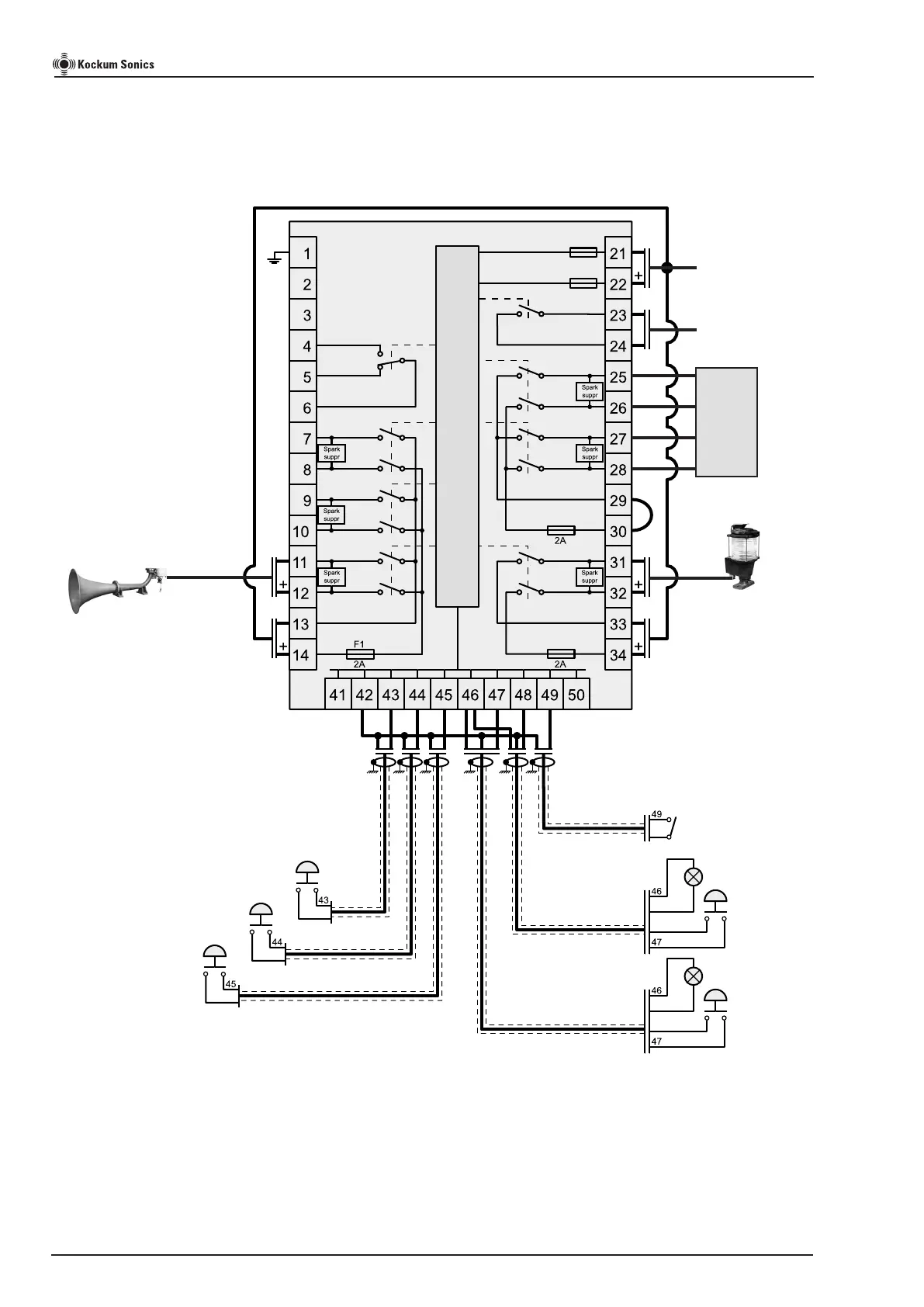
Typical external wiring diagram for Signal Controller (24V DC system)
For one TYFON whistle, MORSE LIGHT, GEA function and electrical Bell&Gong BG 310
PA interrupt for GEA
(yard’s supply)
Output to MORSE LIGHT
Output to Aft SUPERTYFON
Notes.
* A potential free relay output that will change state when an
GEA (General Emergency) alarm is activated on the Control Unit.
Max load 230V AC/1.6A...30V DC/1.6A
Signal Controller
TLG2000
Control Unit
All cables to be shielded and shield connected to ships ground.
For details of switch and LED terminal markings, see page 10.
24V DC power supply for TLG2000,
MORSE LIGHT and TYFON
Page 14 of 20
TLG2000 Signal Controller Instruction Manual
BG 310 connection
terminal
11
8
11
7
common
common
Aground
Anchor
IMPORTANT! See page 8 for
correct supply connection.
For correct operation
of TLG2000 read
page 7 to chose right
mode for Electronic
Bell & Gong.
 Loading...