Do you have a question about the Koden MDC-5204 and is the answer not in the manual?
Details safety measures during maintenance, such as residual high voltage, keeping power off, dust precautions, and static electricity.
Guidance on selecting optimal installation locations for maximum unit performance, considering various factors.
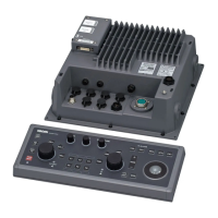
System configuration diagram for the MDC-5204 series, illustrating connections between scanner unit, display unit, antenna, and power sources.
Provides external views and dimensions for RB806 and RB807 scanner units, detailing installation aspects.
Instructions for installing the Antenna Scanner unit, including orientation, mounting holes, and securing with bolts.
Procedure for mounting the antenna onto the scanner unit rotational shaft, including alignment and securing the aerial.
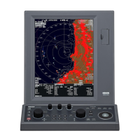
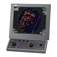
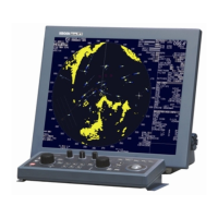
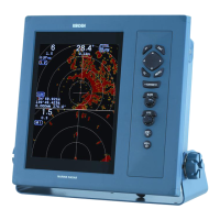
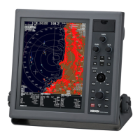
Guidance on mounting display units (MRD-111, MRD-109, MRO-108) using tabletop or panel flush mount methods.
Guides users through initial setup procedures like TUNE, HL OFFSET, TX DELAY, ANT HEIGHT, and other system settings.
Details how to set up input/output interfaces for various data sources like HDG, STW, COG/SOG, and GPS, including NMEA and baud rate settings.
Covers preset adjustments for RAIN, SEA, and GAIN modes, including MIN/MAX and OFFSET settings for optimal clutter suppression.
Provides information for troubleshooting and repairing the radar system, including malfunction detection steps and tables.
Covers on-board repair procedures, including fuse replacement and internal battery replacement.
Detailed procedure for magnetron replacement (RB806), including desoldering wires, removing screws, and cutting excess wires.
| Type | Color LCD |
|---|---|
| Transmitter Output Power | 4 kW |
| Frequency | 9410 MHz ±30 MHz (X-band) |
| Display | Color LCD |
| Antenna Rotation Speed | 24 rpm |
| Power Consumption | 60 W |