Do you have a question about the Koden MDC-5206 and is the answer not in the manual?
Instructions for cable routing and connection between radar components.
Provides a block diagram of the MDC-5204 radar system configuration.
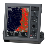
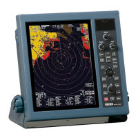
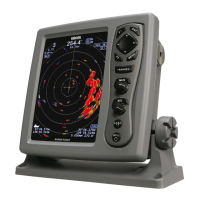
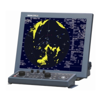
Shows system configuration diagrams for MDC-5206, MDC-5212, and MDC-5225 models.
Illustrates the system configuration for the MDC-5504 radar model.
Displays system configuration diagrams for MDC-5506, MDC-5512, and MDC-5525 models.
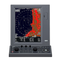
Provides external views and dimensions for MRD-111 and MRD-109 display units.
Identifies the ports on the display unit for various cable connections.
Illustrates cable connections for the MRD-111 display unit, including antenna and power.
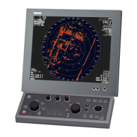
Shows cable connections for the MRD-109 display unit, including antenna, power, and operation unit.
Explains cable connections for cross-over, dual, and master/slave radar system configurations.
Details cable connections for networked radar systems in different configurations.
Describes how to connect a slave display unit to function as a monitor for the master unit.
Covers initial system setup procedures including tuning, offsets, and display settings.
Procedure for performing automatic or manual tune adjustment for optimal radar performance.
Method for adjusting heading offset to compensate for installation misalignment.
Procedure for adjusting transmission delay time to match radar display to actual target distances.
Configures input/output settings for ship's bearing, speed, and AIS data.
Configures heading input from GPS compass or other devices.
Configures the serial data sentences output from NMEA ports.
Configures preset modes for RAIN and SEA clutter suppression.
Adjusts minimum and maximum values for anti-rain clutter suppression in MAN and CFAR modes.
Sets the minimum value for anti-rain clutter suppression, affecting knob adjustments.
Adjusts maximum value for anti-rain clutter suppression, affecting suppression strength.
Configures minimum and maximum settings for sea clutter suppression in MAN and AUTO modes.
Sets the minimum value for sea suppression, moderating knob effects for easier adjustment.
Sets the maximum value for sea clutter suppression, affecting suppression effect at maximum level.
Adjusts display sensitivity based on GAIN knob rotation for MIN and MAX settings.
Sets the minimum GAIN value, moderating knob effects for easier adjustment.
Sets the maximum GAIN value, affecting sensitivity control at maximum GAIN.
Instructions for saving and loading radar setup data and maps to internal or external memory.
A comprehensive list of radar alarms, warnings, and cautions with their causes and contents.
Provides information for troubleshooting and repairing radar system malfunctions.
Outlines basic malfunction diagnostic procedures for common issues like no power or no display.
A flow chart to diagnose basic malfunctions by following a step-by-step process.
Guides through initial checks for common radar startup and operation issues.
Troubleshooting steps for when the radar unit does not power on, checking cables, fuses, and voltages.
Diagnostic steps for when the radar display shows no image, checking brilliance, LEDs, and connections.
Troubleshooting steps for when the antenna unit does not respond, checking cables and system settings.
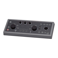
Diagnoses errors related to the operation unit, checking panel connection and key functionality.
Troubleshooting steps for when no radar echoes are displayed, checking tune, settings, and components.
Steps to diagnose and resolve issues with weak radar echo sensitivity.
Troubleshooting for missing heading, speed, or position data, checking NMEA input and configuration.
Troubleshooting steps for AIS data display issues, checking connections and settings.
General category for antenna unit failures.
Specific diagnostic steps for antenna unit failure on the RB806 model.
Diagnostic steps for antenna unit failure specific to RB807, RB808, and RB809 models.
Detailed steps for replacing the magnetron in the radar system.
| Brand | Koden |
|---|---|
| Model | MDC-5206 |
| Category | Marine Radar |
| Language | English |