Do you have a question about the Koden MDC-900 Series and is the answer not in the manual?
Lists cautions related to electrical hazards, dust, location, and static electricity.
Details safety warnings for the rotating aerial and electromagnetic disturbance.
Encompasses warnings against disassembly, fire, high voltage, and display unit handling.
Explains radar screen elements, symbols, and display conventions.
Details the function and operation of each control panel key.
Describes unit power cycling, startup sequence, and language selection.
Guides on adjusting LCD and panel brightness for optimal visibility.
Covers the procedure for starting and stopping the radar transmission.
Details changing observation ranges for main and sub-screens.
Guides on adjusting radar gain for optimal image clarity.
Explains STC to suppress sea clutter for better target visibility.
Lists functions assignable to F1/F2 keys and their usage.
Describes how to temporarily delete the heading line for clearer viewing.
Explains how to move and use the crosshair cursor for measurements.
Guides using the crosshair cursor for distance and bearing measurements.
Details connecting and displaying CCD camera video on the radar screen.
Explains navigation and usage of the radar's menu system.
Guides using FTC to reduce rain/snow clutter for clearer detection.
Covers display modes like H UP, N UP, C UP, and RM/TM motion.
Explains resetting True Motion display when ship exits movable range.
Details options for displaying radar images: PPI, PPI/PPI, PPI/NAV.
Describes how to shift the radar display's center point.
Explains enlarging small targets for better visibility.
Guides on stabilizing unstable target signals for clearer display.
Details selecting pulse width for optimal target detection.
Explains displaying target trails to visualize movement over time.
Guides on using the Electronic Bearing Line for measuring bearings.
Explains using the Variable Range Marker for measuring distances.
Details adjusting display colors for improved visibility.
Allows changing the shape and extension of the crosshair cursor.
Explains displaying parallel lines for navigation assistance.
Covers setting bearing display as true or relative to north.
Describes displaying vectors representing heading and speed of ships.
Guides setting IN/OUT alarms for target detection within specified ranges.
Explains sleep mode for power saving and its alarm combination.
Details displaying information received from other ships via AIS.
Covers Automatic Tracking features for targets, including acquisition and display.
Explains accessing and navigating the system's menu structure.
Covers setting up supplementary functions for effective radar use.
Guides adjusting the radar image's bearing for accurate alignment.
Explains matching radar target distance with actual distances.
Details the Minimum Bandwidth Suppression feature to reduce transmission leaks.
Guides adjusting STC curve based on antenna height for sea clutter.
Covers selecting AUTO or MANUAL tuning for optimal reception frequency.
Explains automatic tuning for best performance after installation.
Guides manual tuning when environmental conditions affect reception.
Details setting pulse width for different ranges and priorities.
Explains using IR to eliminate noise from other radars.
Guides changing image colors for better echo discrimination.
Covers selecting input signals from antenna, monitor, or demo.
Allows adjustment of display's visibility angle for better viewing.
Covers setting NMEA data transmission speeds for external equipment.
Explains customizing radar settings like F1/F2 keys and display colors.
Introduces the system menu for maintenance and self-diagnosis.
Provides procedures for periodic inspection and cleaning of the radar equipment.
Details monthly checks for LCD filter and antenna surface.
Outlines yearly checks for antenna drive motor brushes.
Instructions on replacing a blown fuse and safety warnings.
Discusses the magnetron as a consumable needing periodic replacement.
Guides on troubleshooting radar issues and information for repair.
Explains using the built-in self-diagnostic feature for problem identification.
Provides a table of troubleshooting steps for various radar problems.
Covers determining optimal location and mounting the radar antenna.
Details wiring procedures for connecting radome and open antennas.
Guides on installing the display unit on desktop or flush-mounting.
Outlines crucial checks and adjustments required after installation.
Provides a comprehensive diagram for connecting components to the display unit.
Details pin configurations for all rear panel connectors.
Explains how to connect the DC power cable.
Guides on connecting an optional AIS receiver.
Details connecting navigation equipment using NMEA ports.
Explains connecting external audio/visual alerts.
Guides on connecting an optional CCD camera for video display.
Provides a list of NMEA sentences supported for input and output.
Presents a detailed mapping of menu items and their settings.
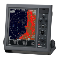
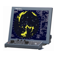
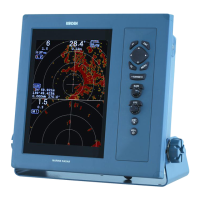
Lists the technical specifications for different MDC-900 series models.
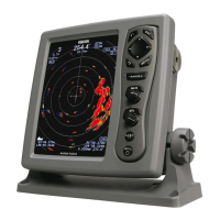
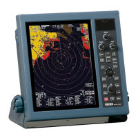
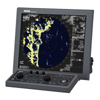
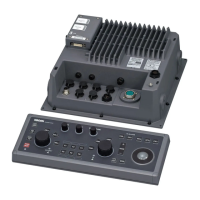
Provides dimensional drawings and external views of the equipment.
Explains the basic functionality and components of a radar system.
Describes side lobes and their effect on radar performance.
Explains antenna beam width and its impact on resolution.
Discusses radio wave propagation and interaction with targets.
Explains sources of radar interference and how to reduce them.
| Power Output | 4 kW |
|---|---|
| Range Resolution | 10 m |
| Power Supply | 12/24 V DC |
| Range | 0.0625 to 96 NM |
| Antenna Rotation Speed | 24 rpm |
| Input Voltage | 12/24 V DC |