Do you have a question about the Koden MDC-7060 and is the answer not in the manual?
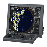
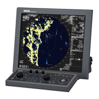
Overview of the radar display layout, including screen sections and information panels.
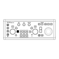
Detailed description of the radar's control panel keys, knobs, and indicators.
Instructions for navigating and operating the radar through its menu system.
How to use the trackball and ENT key for direct function access.
Step-by-step guide for turning the radar system on and off.
How to adjust the brightness of the display and operation panel.
Procedures for enabling and disabling radar transmission mode.
Adjusting manual and auto tuning for optimal radar performance.
How to adjust the radar's coverage area and range units.
Methods for adjusting receiver gain for better target detection.
Techniques to suppress sea clutter for clearer display.
Methods to reduce clutter caused by weather conditions.
Adjusting pulse width for target detection at different ranges.
Options for Head Up, Course Up, and North Up display modes.
Setting stabilization modes for accurate target tracking.
Using Range Rings and Variable Range Markers for distance measurement.
Using Electronic Bearing Lines for bearing measurement.
Configuring bearing display modes (True/Relative).
Using Parallel Index lines for distance and bearing measurements.
Using ERBL for distance and bearing measurements.
Adjusting display colors and brightness for day/night conditions.
Temporarily hiding heading and navigation data for better target visibility.
Displaying target trails for tracking and collision avoidance.
Adjusting the display center for a wider view in the heading direction.
How to assign and use the dedicated function keys for quick access.
Selecting predefined picture modes for various conditions.
Suppressing clutter and improving target visibility using echo processing.
Enlarging target images for easier viewing.
Reducing interference from other radars.
Adjusting the contrast for better signal differentiation.
Removing white noise and other signals for a cleaner picture.
Removing unwanted signals based on echo color.
Changing transmission pulse width for optimal target detection.
How to receive signals from Radar Beacons, SART, and Radar Enhancers.
Setting up two radars to be connected together.
Displaying cursor data in distance/bearing and latitude/longitude.
Setting the reference point and display center for measurements.
Setting the ship's outline and antenna position relative to CCRP.
Function for river navigation, showing ferry mode and heading line.
Adjusting display settings like ALL PPI mode and rotation margin.
Recommendations for maneuvering based on SOG and COG for collision prevention.
Setting fan-type alarm areas for target detection.
Alarms when echoes enter or leave a defined map area.
Alarms when tracked targets enter a guard zone.
Alarms when the ship crosses a predefined navigation line.
Displays a list of currently active alarms.
Displays a list of past alarms.
Setting auto-acquisition alarm functions for TT and AIS.
General settings for target vectors, time, and stabilization.
Automatic Identification System features and display options.
Tracking functions for target acquisition and collision avoidance.
Simulating own ship's movement for anti-collision planning.
Displays parallel lines to the heading for navigation reference.
Blinking HL marker to confirm absence of small targets.
Displays a dotted line towards the stern for reference.
Displays a barge icon for river operations, adjustable size.
Controls the overall display of the MAP function.
Records and displays the past track of the own ship.
Sets up and displays past track positions for targets.
Allows users to create and display coast lines for navigation.
Displays navigation lines for visual navigation aid.
Allows users to set up routes for visual navigation aid.
Displays various marks on designated places for signs or areas.
Input points connected by a line for visual navigation and alarms.
Displays ROUTE information from external devices.
Displays Waypoint (WPT) name information from external devices.
Associates a label number with each target track.
Defines the datum to which position locations are referenced.
Allows users to enter custom datum names.
Selects offset input of position (DTM, MAN).
Displays buoy information received from a connected GPS BUOY.
Displays a flag at the first waypoint of a route or waypoint.
Enables display of geographical latitude and longitude lines.
Displays C-MAP charts from an inserted SD-card.
Access point for system-related settings.
Adjusting the radar's time settings.
Managing user profiles, saving settings, and editing names.
Configuring sound, key click, and external buzzer settings.
Switching the user interface language between English and Japanese.
Reducing radar information items for a wider view.
Enabling or disabling the help window for operations.
Access point for maintenance functions like startup and backup.
Saving and restoring radar setup data to internal or external memory.
Viewing and resetting total operating and transmitting hours.
Simplifying the menu by turning unused items ON or OFF.
Confirming firmware version and updating the system program.
Explanation of how a radar system works, including components and principles.
Properties of radar waves, including beam width and reflected targets.
Understanding and reducing interference from other radars.
Procedure to troubleshoot issues with the alarm sound.
Testing keys and knobs on the operation unit for functionality.
Diagnosing issues when the TT (ARPA) function is not working.
Troubleshooting steps for when AIS data is not displayed.
Checking serial input from connected devices.
Diagnosing issues when no radar video is shown on the display.
Procedures for troubleshooting a frozen or unresponsive display.
Explains alarm categories, display, and confirmation procedures.
Technical specifications for the antenna and scanner components.
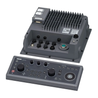
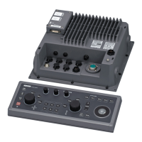
Specifications for the display, processor, and operation units.
Physical dimensions and external views of the main units.
Detailed hierarchical view of the radar's menu structure.
Explains special functions performed using key combinations.
Formats for various NMEA data inputs like Heading, Speed, and Position.
Formats for TT tracking data output, including target labels and messages.
Formats for radar system and own ship data output.
Specifications for serial data interfaces (NAV, EPFS, SDME, AIS).
| Type | Marine Radar |
|---|---|
| Power Output | 6 kW |
| Rotation Speed | 24 rpm |
| Antenna Length | 4 ft |
| Frequency | 9410 MHz |
| Display | Color LCD |
| Power Supply | 12-24 VDC |