Do you have a question about the Koden MDC-7025 and is the answer not in the manual?
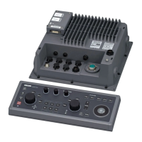
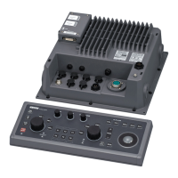
Covers external views, dimensions, mounting, and connecting cables for the antenna scanner.
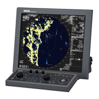
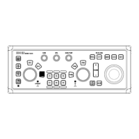
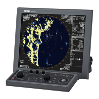
Instructions for installing display and operation units, including various mounting types.
Details on connecting external monitors, VDR, alarm outputs, gyro, and navigation devices.
Essential setup procedures for radar operation, including tuning and adjustments.
Details required for repair requests and an overview of self-diagnostic capabilities.
Comprehensive lists of alarms, warnings, cautions, operation notes, and their causes.
Step-by-step troubleshooting guides and flowcharts for common radar malfunctions.
| Type | Color LCD |
|---|---|
| Frequency | 9410 MHz (X-band) |
| Display | Color TFT LCD |
| Operating Voltage | 10.8 - 31.2 VDC |
| Weight | 4.5 kg (display unit) |