TP-5867 11/02 25Section 4 Controller Troubleshooting
Relay Description Relay Label
Starter K1 or SR
Ignition K5 or IR
Control Power K25
Crank CC
Cyclic Crank K21
Off/Reset O/RS
Figure 4-5 System Relays (not located on the
controller circuit board)
1
B-358095-
7
3
456
8
9
10
12
2
13
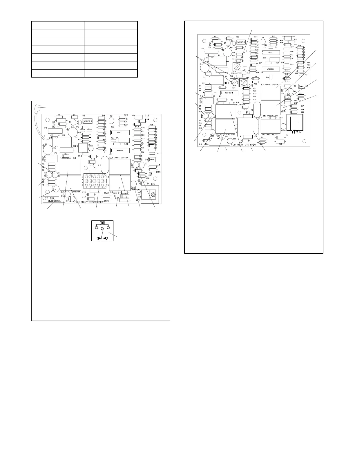
1. LED1
2. Fault latching in AUTO lead 4
3. LED3
4. LED4
5. K3 relay
6. K4 relay
7. K1, K2, K3, K4 relay schematic
8. P1 connector
9. K2 relay
10. K1 relay
11. Circuit board part number
12. LED2
13. LED5
11
Figure 4-6 Basic Controller Circuit Board 358095
13
GM10064-
11
3
10
2
6
8
14
12
5
1. Overspeed adjustment potentiometer, R17
2. K4 crank disconnect relay
3. LED4
4. K5 crank/flash relay
5. LED5
6. P1 connector
7. Circuit board ID number
8. K2 fault shutdown relay
9. Circuit board ID number (alternate location)
10. K3 start/run relay
11. LED3
12. LED2
13. LED1
14. K1 external fault latch relay
15. Cyclic crank potentiometers
1
7
9
4
15
Figure 4-7 Integrated Controller Circuit Board
GM10064