TP-5867 11/02 1Section 1 Specifications
Section 1 Specifications
1.1 Introduction
The spec sheets for each generator set provide specific
generator and engine information. Refer to the
respective spec sheet for data not supplied in this
manual. Consult the generator set installation manual,
engine operation manual, and engine service manual
for additional specifications.
1.2 Controller Features
The generator set is equipped with a relay controller.
For a specific description of the controller, see
Section 2, Operation, in the operation manual.
Controller features include the following:
D Fault shutdowns:
D Overcrank
D Overspeed
D Pressure, low oil
D High engine temperature
D Running time meter
D Switches and standard features:
D Master switch, RUN/RESET-OFF/AUTO
D Cranking, cyclic
D Line circuit breaker
D Common fault lamp (on some controllers)
1.3 Alternator
The generator is equipped with Kohler’s PowerBoostt
voltage regulation system, which provides instant
response to load changes.
PowerBoostt is a unique system that ensures reliable
motor starting and consistent voltage levels.
PowerBoostt utilizes a voltage monitoring system that
employs a winding independent of the field to monitor
and stabilize voltage.
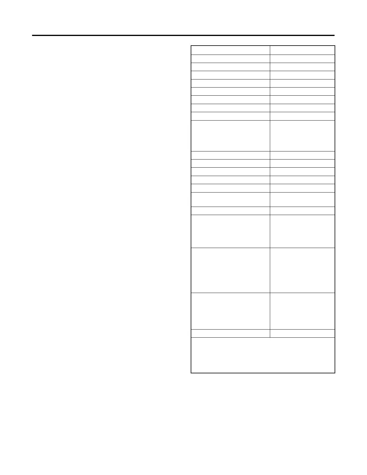
See Figure 1-1 for alternator specifications.
Alternator Specification 8.5/11RMY
Frequency Hz 50/60
Phase Single-Phase
Number of leads 4
Excitation method Static Excited
Voltage regulator type
PowerBoosttIIIE
Coupling type Direct
Thrubolt torque, Nm ( ft. lb.) 38 (28)
Overbolt torque, Nm (in. lb.) 7 (60)
Insulation (rotor and stator) Epoxy varnish, vacuum
impregnated
Units built before 7/1/02 Class 155
Units built after 7/1/02 Class 180
Winding material Copper
Bearing, number and type 1, replaceable ball
Circuit protection
Controller 10 amps
Voltage regulator 10 amps
Generator AC output
Dependent on voltage
configuration
Rotor resistance, ohms, cold 4.0
Stator resistance, ohms,* cold
Leads: 1-2, 3-4 0.07
33-44 0.07
55-33 0.70
Stator output voltage with
separately excited rotor using
12-volt battery, minimum
Leads: 1-2, 3-4 132V
33-44 132V
55-33 145V
Rotor field voltage/current
readings at rated output
voltage, hot
No load 8V/2.5 amps
Full load 47V/7.4 amps
Brush length, new 19.05 mm (0.75 in.)
* Most ohmmeters do not give accurate readings when
measuring less than 1 ohm. The stator can be considered
good if a low resistance reading (continuity) is obtained and
there is no evidence of shorted windings (discoloration). Do
not confuse a low resistance reading with a reading indicating a
shorted winding.
Figure 1-1 Alternator Specifications