EasyManua.ls Logo

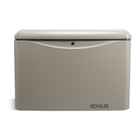
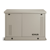
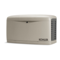
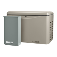
Kohler 18RESL

Kohler 18RESL
100 pages
To Next Page IconTo Next Page
Loading...
Residential/Commercial Generator Sets
Models:
17RES/RESL/RESNT
18RES/RESL/RESNT/TRES
Controllers:
ADC-RES Advanced Digital Control
DC-RET Digital Control
TP-6519 8/17c
Service

Table of Contents

Other manuals for Kohler 18RESL

Questions and Answers:

Kohler 18RESL Specifications

General IconGeneral
BrandKohler
Model18RESL
CategoryPortable Generator
LanguageEnglish

Summary

Service

ResidentialCommercial Generator Sets

Covers generator sets for residential and commercial applications.

Models

Lists the specific generator set models covered in the manual.

Controllers

Identifies the types of controllers used with the generator sets.

Safety Precautions and Instructions

Accidental Starting

Details hazards and procedures related to accidental generator set starting.

Battery

Covers safety warnings and procedures for handling batteries and electrolyte.

Combustible materials

Discusses fire hazards from fuel and fuel vapors, and fire extinguisher use.

Exhaust System

Warns about carbon monoxide hazards from exhaust fumes.

Fuel System

Highlights explosion hazards from fuel vapors.

Hazardous Noise

Warns about potential hearing loss from generator noise.

Hazardous VoltageMoving Parts

Covers dangers of hazardous voltage and moving parts.

Heavy Equipment

Discusses safe lifting procedures for heavy generator components.

Hot Parts

Warns about severe injury or death from hot engine and exhaust system parts.

Introduction

List of Related Materials

Lists other manuals and documentation relevant to the generator set.

Service Assistance

Contacting Kohler Service

Provides contact information and resources for obtaining service assistance.

Section 1 Specifications

1.1 Introduction

Explains the purpose of specification sheets and other manuals.

1.2 Controller Specifications

Details the environmental and power requirements for the controller.

1.3 Engine Service

Describes the engine type and refers to the engine service manual.

1.4 Engine Specifications

Lists detailed specifications for the generator set engine.

1.5 Alternator Specifications

Provides technical specifications for the generator set alternator.

1.6 Torque Specifications

Lists specific torque values for various fasteners.

1.7 Service Views

Illustrates the location of various components on the generator set.

Section 2 Scheduled Maintenance

Generator Set Service

Advises to follow safety precautions before servicing the generator set.

Routine Maintenance

Guides on determining when to schedule routine maintenance.

2.1 Service Schedule

Outlines maintenance tasks and their intervals for the generator set.

Figure 2-1 Service Schedule

Provides a detailed service schedule table with procedures and intervals.

2.2 Lubrication System

Covers oil change intervals and procedures for the lubrication system.

2.2.1 Low Oil Pressure Shutdown

Explains the low oil pressure shutdown feature and its limitations.

2.2.2 Oil Check

Details how to check the engine oil level and recommended oil type.

2.2.3 Engine Oil Recommendation

Specifies the recommended API service class and viscosity for engine oil.

2.2.4 Oil Change Procedure

Provides a step-by-step guide for draining and refilling engine oil and replacing the filter.

2.2.5 Oil Cooler

Instructs on inspecting and cleaning the oil cooler.

2.3 Spark Plugs

Guides on checking, adjusting, and replacing spark plugs.

2.4 Air Cleaner Service

Details how to service the air cleaner element and components.

Paper Element Service

Explains the procedure for replacing the paper air cleaner element.

2.5 Cooling System

Advises on keeping cooling inlets and outlets clean and unobstructed.

2.6 Stepper Motor Coupling

Instructs on replacing the stepper motor coupling and bushings.

2.7 Exhaust System

Covers precautions for the exhaust system and inspection points.

2.8 Battery

Provides safety warnings and procedures for battery maintenance.

Battery gases

Warns about explosion hazards from battery gases.

Battery short circuits

Details hazards and precautions for preventing battery short circuits.

2.9 Battery Charger

Explains the function of the battery charger and periodic maintenance.

2.10 Storage Procedure

Outlines the procedure for storing the generator set for extended periods.

2.10.1 Lubricating System

Details lubricating system preparation for storage.

2.10.2 Fuel System

Describes fuel system preparation for storage.

2.10.3 Cylinder Lubrication

Explains cylinder lubrication for storage.

2.10.4 Exterior Preparation

Covers exterior preparation for storage.

2.10.5 Battery

Details battery preparation for storage.

Section 3 Troubleshooting

3.1 Introduction

Introduces troubleshooting procedures and refers to other manuals.

3.2 Initial Checks

Lists common problems to check before replacing parts.

3.3 Troubleshooting Chart

Provides a chart to diagnose and correct common generator set problems.

Generator set engine does not crank

Details troubleshooting steps for when the generator set engine does not crank.

Cranks but does not start

Provides troubleshooting steps for when the generator set cranks but does not start.

Starts hard

Addresses troubleshooting for hard starting conditions.

Starts but shuts down

Provides troubleshooting for generator sets that start but shut down.

Stops suddenly

Details troubleshooting for generator sets that stop suddenly.

Overheats

Provides troubleshooting steps for generator set overheating.

Noisy operation

Addresses troubleshooting for noisy generator set operation.

Operates erratically

Details troubleshooting for erratic generator set operation.

Lacks power

Provides troubleshooting for generator sets lacking power.

Low output or excessive drop in voltage

Details troubleshooting for low output voltage or excessive voltage drop.

No output voltage

Provides troubleshooting steps for no output voltage.

3.4 Controller Troubleshooting

Provides troubleshooting steps for controller-related issues.

Section 4 Controller

4.1 Introduction

Introduces the controller section and its scope.

Figure 4-1 Controller Components

Illustrates the components of the generator set controller.

4.2 Controls and Display

Describes the controls and displays of the ADC-RES and DC-RET controllers.

4.2.1 Master Switch

Explains the operation of the generator set master switch.

4.2.2 LED Display

Details the information displayed by the LED display.

Figure 4-4 Controls and Indicators

Lists and describes various controls and indicators on the controller.

4.2.3 Keypad

Explains the function and use of the ADC-RES controller keypad.

4.3 Sequence of Operation

Describes the controller's sequence of operation for start, run, and stop.

4.3.1 Starting Sequence, Master Switch Moved to RUN

Details the starting sequence when the master switch is in RUN.

4.3.2 Starting Sequence, Remote Start

Explains the starting sequence for remote start operations.

4.3.4 Stopping Sequence, Master Switch Moved to OFFRESET

Explains the stopping sequence via the master switch.

4.3.5 Stopping Sequence, Remote Stop

Details the stopping sequence via remote stop.

4.3.6 Standby Mode

Describes the standby mode operation of the controller.

4.3.7 Sleep Mode

Explains the sleep mode function of the controller.

4.4 Faults

Lists and describes warning and shutdown fault codes.

4.4.1 Warnings

Details fault codes that trigger warnings but not shutdowns.

4.4.2 Shutdowns

Lists fault codes that cause the generator set to shut down.

Figure 4-7 Fault Codes

Lists specific fault codes, their descriptions, and checks.

4.5 Controller Configuration and Adjustment, ADC-RES

Provides instructions for configuring and adjusting the ADC-RES controller.

4.5.1 Controller Configuration

Explains how to check and change controller configuration settings.

4.5.4 Voltage and Frequency Adjustments

Guides on adjusting generator output voltage and frequency.

4.6 Controller Relays

Identifies controller relays and associated LEDs.

Figure 4-10 Optional Relay Board

Shows the optional relay board connections.

Figure 4-11 Connection to Controller Circuit Board

Illustrates the connection of harnesses to the controller circuit board.

Figure 4-12 Relay Board Connection Harness

Details the wiring connections for the relay board harness.

4.8 Silicon Controlled Rectifier Module

Explains the function and testing of the SCR module.

SCR Module Test Procedure

Details the procedure for testing the SCR module using various equipment.

4.9 Controller Replacement

Provides instructions for replacing the controller.

Controller Replacement Procedure

Outlines the steps for replacing the generator set controller.

Logic Board Replacement Procedure

Details the steps for replacing the controller logic board.

Controller setup

Guides on setting up the controller after replacement.

Figure 4-20 Controller Settings

Lists and defines various controller settings and parameters.

Section 5 Component Testing and Adjustment

5.1 Theory of Operation

Explains the operational theory of the generator set's rotating-field alternator.

5.2 Separate Excitation

Describes the procedure for separate excitation to test the generator.

Figure 5-2 Generator Troubleshooting

Provides a flowchart for generator troubleshooting.

Separate Excitation Procedure

Details the step-by-step procedure for using an external voltage source for excitation.

5.3 Stator

Covers stator inspection and continuity/resistance testing.

Stator Continuity and Resistance Tests

Provides procedures for testing stator continuity and resistance.

Figure 5-7 Continuity Test Results on a Good Stator (single-phase)

Lists continuity test results for single-phase stators.

5.4 Main Field (Rotor)

Covers rotor inspection and continuity/resistance testing.

5.4.1 Rotor Continuity and Resistance Tests

Provides procedures for testing rotor continuity and resistance.

5.5 Slip Rings

Describes the appearance and cleaning of slip rings.

5.6 Brushes

Covers brush function, causes of arcing, and replacement criteria.

5.7 Voltage Connections

Shows how generator set voltage is connected.

5.7.1 Voltage Connections, Single-Phase Models

Details voltage connections for single-phase models.

5.7.2 Voltage Connections, 3-Phase Models

Details voltage connections for three-phase models.

5.7.3 Voltage Regulation

Explains how voltage regulation is performed by the controller and SCR module.

5.8 Voltage Adjustment (ADC-RES only)

Guides on adjusting generator output voltage using the ADC-RES controller.

5.8.2 Volts per Hertz (Hz) Adjustments (Droop)

Guides on adjusting volts per hertz for voltage droop.

Figure 5-19 Output Voltage and Frequency Adjustments

Illustrates the procedure for adjusting output voltage and frequency.

Figure 5-20 Output Voltage and Frequency Adjustments, Continued

Continues the illustration for adjusting output voltage and frequency.

Figure 5-21 Save Mode

Illustrates the procedure for saving settings in adjustment mode.

5.9 Governor System

Explains the governor system, including stepper motor and magnetic pickup.

5.9.1 Operation

Describes the operation of the engine governor system.

5.9.2 Initial Checks and Operation Test

Provides initial checks and tests for the governor system.

5.9.3 HuntingSurging

Discusses causes of hunting/surging and preliminary checks.

5.9.4 Governor SystemMagnetic Pickup Operation Test

Details the procedure for testing the governor system and magnetic pickup.

5.9.5 Frequency Adjustment

Guides on adjusting generator output frequency using the ADC controller.

5.10 Fault Shutdown Tests

Provides tests to verify generator set fault shutdown functions.

5.10.1 Controller Fault Shutdown Functions

Details tests for overspeed, overcrank, and high engine temperature shutdowns.

5.10.2 Fault Shutdown Switches

Covers testing of low oil pressure and high engine temperature shutdown switches.

Temperature Sensor (CTS)

Explains how to test the coolant temperature sensor.

Low Oil Pressure (LOP) Switch

Explains how to test the low oil pressure switch.

5.11 Generator Set Master Switch

Details the generator set master switch and its continuity checks.

5.12 Fuel Systems

Covers the generator set's fuel system and troubleshooting.

5.12.1 Fuel Solenoid Valve

Explains the function of the fuel solenoid valve and its test procedure.

5.12.2 Fuel Regulators

Describes the fuel regulators and how to check fuel pressure.

5.12.3 Fuel Conversion

Provides instructions for converting the fuel system between natural gas and LP.

5.12.4 Digital Spark Advance Ignition (DSAI) Timing

Explains DSAI timing and connection procedures for different fuels.

5.13 Circuit Protection

Covers circuit protection devices like circuit breakers and fuses.

5.13.1 Line Circuit Breaker

Explains the function and operation of the line circuit breaker.

5.13.2 Fuses

Lists fuse ratings, labels, and part numbers.

5.14 Starter Relay

Describes the starter relay and its connections.

5.15 Continuity Checks

Provides procedures for checking component continuity using an ohmmeter.

Section 6 DisassemblyReassembly

6.1 Initial Steps

Outlines initial safety precautions and preparation steps before disassembly.

Remove enclosure

Details the steps for removing the generator set enclosure.

Generator Disassembly

Provides steps for disassembling the generator components.

Section 7 Wiring Diagrams

Figure 7-1 Wiring Diagrams and Schematics

Lists the available wiring diagrams and their corresponding page numbers.

Figure 7-2 Schematic Diagram, Single Phase, ADV-7353-F

Provides the schematic diagram for single-phase generator sets.

Figure 7-3 Point-to-Point Wiring Diagram, Single Phase, GM52541-E

Shows the point-to-point wiring diagram for single-phase models.

Figure 7-4 Schematic Diagram, Three-Phase (TRES Models), ADV-7637

Provides the schematic diagram for three-phase generator sets.

Figure 7-5 Point-to-Point Wiring Diagram, Three-Phase (TRES Models), GM65661

Shows the point-to-point wiring diagram for three-phase models.

Appendix A Abbreviations

Abbreviations List

Lists common abbreviations used throughout the publication.

Appendix B Common Hardware Application Guidelines

BoltScrew Length

Provides guidelines for determining appropriate bolt and screw lengths.

Washers and Nuts

Guides on the use of washers and nuts in assembly.

Appendix C General Torque Specifications

American Standard Fasteners Torque Specifications

Lists torque specifications for American standard fasteners.

Metric Fasteners Torque Specifications, Measured in Nm (ft. lb.)

Lists torque specifications for metric fasteners.

Appendix D Common Hardware Identification

ScrewBoltsStuds Head Styles

Identifies common screw, bolt, and stud head styles.

Nuts Nut Styles

Identifies common nut styles.

Washers Washer Styles

Identifies common washer styles.

Appendix E Common Hardware List

American Standard

Lists part numbers and dimensions for American standard hardware.

Metric

Lists part numbers and dimensions for metric hardware.

Related product manuals