TP-6519 8/17 47Section 4 Controller
9. Check that the replacement board is positioned so
that the display shows through the opening in the
cover plate and then press the board onto the
standoffs. Check that all corners are securely
mounted.
10. Reconnect all cables and harnesses to the board.
See the wiring diagram in Section 7 for
connections.
Note: Connector P12 on the logic board is not
used at this time.
Replacing the user interface membrane
11. Disconnect the membrane ribbon cable from
connector P8 on the logic board.
12. Carefully remove the membrane from the junction
box cover.
13. Remove the protective backing to expose the
adhesive on the new membrane.
14. Thread the new membrane’s ribbon cable through
the small rectangular opening in the cover. Line up
the membrane window with the larger rectangular
opening.
15. Press the membrane firmly into place.
16. Connect the ribbon cable to the P8 connector on
the logic board.
Controller setup
17. Replace the junction box cover and tighten the four
cover screws.
18. Verify that the generator set master switch is in the
OFF position.
19. Reconnect the engine starting battery, negative (--)
lead last.
20. Reconnect power to the battery charger.
21. Replace the door and tighten the two door screws.
22. Replace the enclosure roof if it was removed.
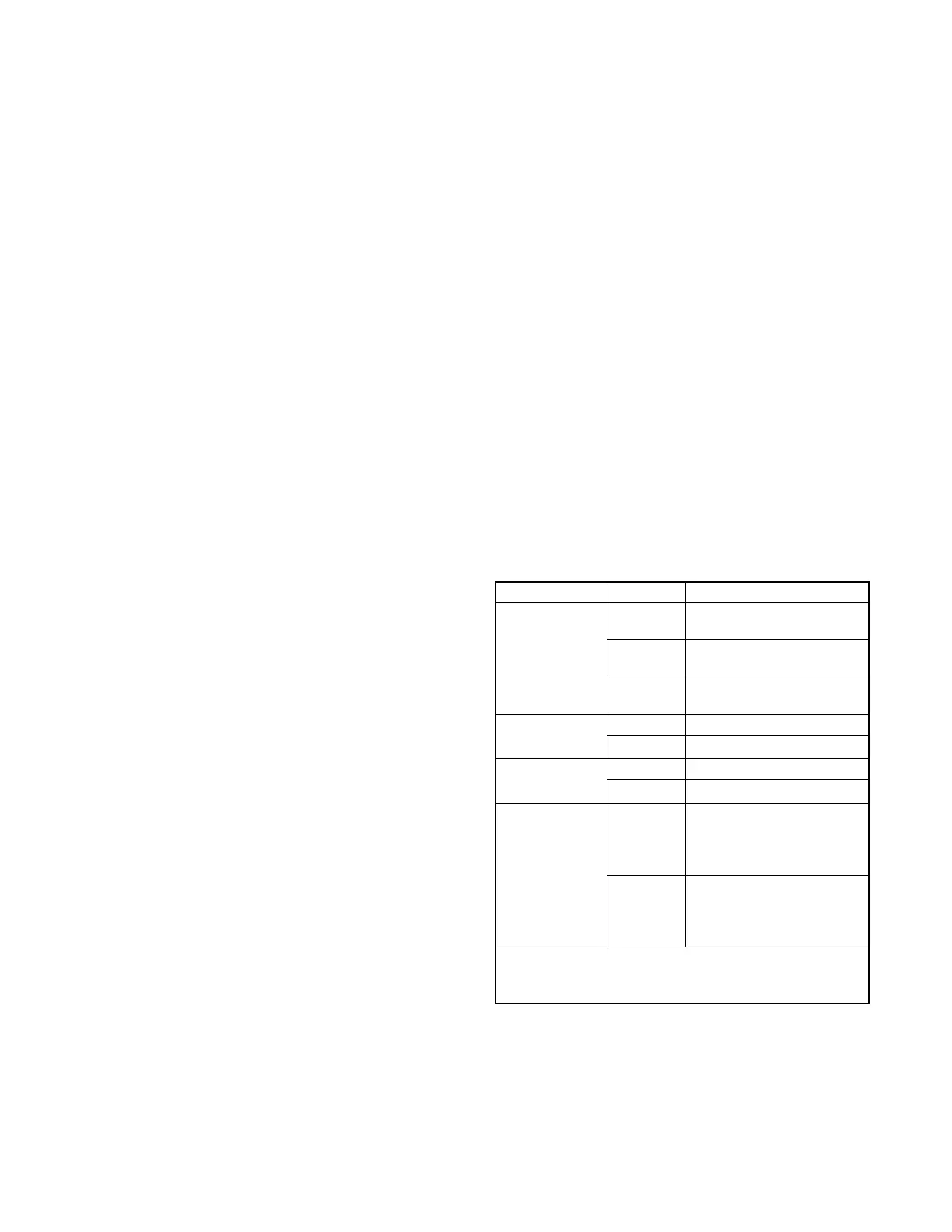
23. Check settings and adjustments for the ADC-RES
controller only:
a. Follow the instructions in the generator set
installation manual to change the new
controller’s configuration settings to match the
generator set system voltage/frequency and
unit c onfiguration. See Figure 4-20.
Check the Uc setting for controller type. The Uc
setting can be changed only once. The default
setting for service replacement controllers is
Uc05, controller type DC-RET (retail model).
Change it to Uc01 to set the controller type to
ADC-RES (distributor model).
b. Use a v oltmeter to check the output voltage.
Follow the instructions in Sections 4.5.4,
Voltage and Frequency Adjustments, and 5.8,
Voltage Adjustment, to adjust the output
voltage and stability.
c. Check the output frequency. Follow the
instructions in Sections 4.5.4, Voltage and
Frequency Adjustments, and 5.9.5, Frequency
Adjustment, to adjust the output frequency and
stability.
24. Place the generator set master switch in the AUTO
position if an ATS or remote start/stop switch is
used.
25. Close and latch the enclosure roof.
Parameter Setting Definition
Unit’s system
voltage and
frequency
Uu01 Single phase, 60 Hz,
120/240 VAC
Uu03 Three-phase, 50 Hz,
230/400 VAC (TRES)
Uu06 Single phase, 50 Hz,
115/230 VAC
Controller type Uc01 ADC-RES (distributor)
Uc05 ] DC-RET (retail) ]
Engine type Ec00 8.5/12RES
Ec12 18RES
Communication
setting *
Cn00 No J1939 communication.
Sleep mode enabled
(48-hour power down in
AUTO).
Cn01 [ J1939 communication
enabled. Sleep mode
disabled (no power down in
AUTO).
* Controller application code version 1.13 or higher.
[ Default setting for application code version 1.13 or higher.
] Default setting for service controllers.
Figure 4-20 Controller Settings
 Loading...


