TP-6519 8/1756 Section 5 Component Testing and Adjustment
Note: The controller will time out and exit the
adjustment mode after approximately 1 minute if
no buttons are pressed. Any unsaved changes
are discarded if the controller times out before the
settings are saved. Refer to Section 4.5 for
instructions to save your settings.
Voltage Adjustment. Adjusts generator output
between 100 and 130 volts.
Gain (Stability) Adjustment. Fine tunes regulator
circuitry to reduce light flicker.
Volts/Hz Adjustment (voltage droop). Determines
frequency (Hz) at which generator output voltage
begins to drop. The controller maintains generator
output at the specified voltage under load until the
generator engine speed drops to a preset level (see
Figure 5-16 for cut-in frequencies). Then the controller
allows the generator voltage and current to drop. The
voltage/current drop enables the engine to pick up the
load. When the generator speed returns to normal (60
Hz or 50 Hz) as load is accepted, the generator output
also returns to normal. See Section 5.8.2 for
instructions to adjust the voltage droop.
Hazardous voltage. Moving parts.
Will cause severe injury or death.
Operate the generator set only when
all guards and electrical enclosures
areinplace.
DANGER
Short circuits. Hazardous voltage/current will cause
severe injury or death. Short circuits can cause bodily injury
and/or equipment damage. Do not contact electrical
connections with tools or jewelry while making adjustments or
repairs. Remove all jewelry before servicing the equipment.
Grounding electrical equipment. Hazardous voltage will
cause severe injury or death. Electrocution is possible
whenever electricity is present. Ensure you comply with all
applicable codes and standards. Electrically ground the
generator set, transfer switch, and related equipment and
electrical circuits. Turn off the main circuit breakers of all
power sources before servicing the equipment. Never contact
electrical leads or appliances when standing in water or on wet
ground because these conditions increase the risk of
electrocution.
5.8.1 Voltage Adjustment Procedure
Refer to Figure 5-19 through Figure 5-21 during the
adjustment procedure.
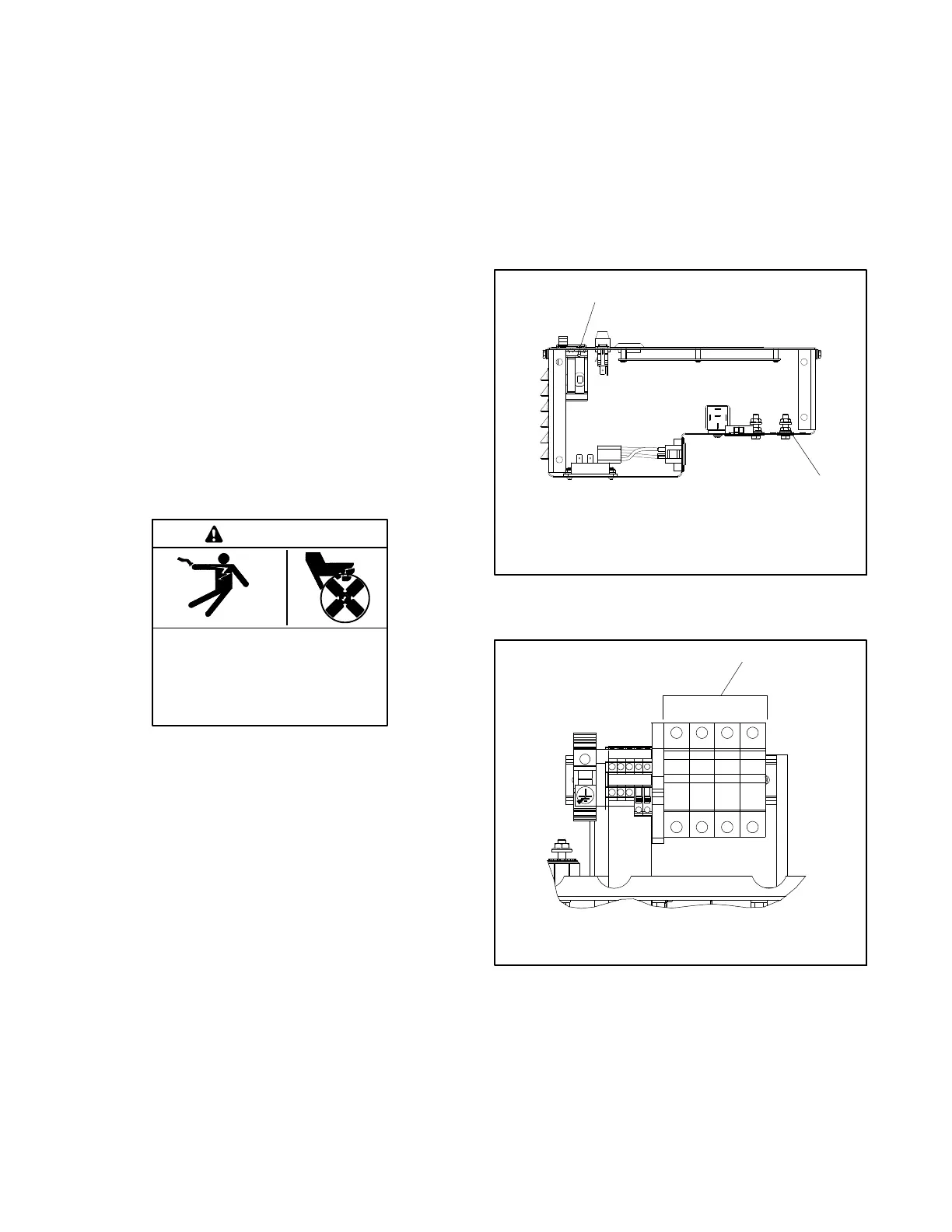
1. Connect a digital voltmeter from one side of the
circuit breaker (L) to the L0 terminal inside the
controller assembly. See Figure 5-13. For
3-phase models. connect the voltmeter from L0 to
L1, L2, or L3 on the circuit breaker. See
Figure 5-14. Set the meter to measure AC volts.
GM57962
1. Line circuit breaker (L)
2. Terminal L0
2
1
Figure 5-13 Circuit Breaker and L0 Terminal
Location, Single-Phase Models
GM66010
L0 L1 L2 L3
1
1. Measure voltage across circuit breaker terminals L0 and L1,
L2, or L3
Figure 5-14 Voltage Measurement, Three-Phase
Models
 Loading...


