TP-6519 8/1746 Section 4 Controller
Controller Replacement Procedure
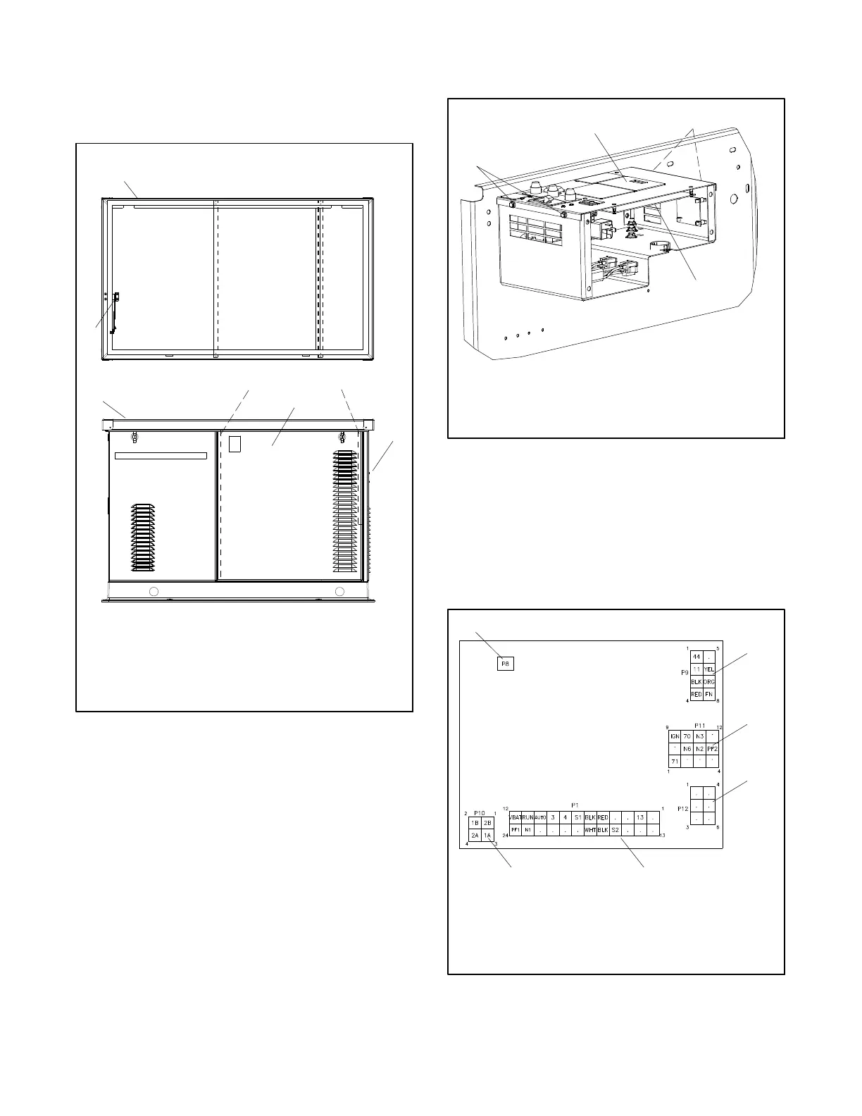
1. Open the enclosure roof. Prop the roof open using
the roof stay or remove the r oof if desired. See
Figure 4-17.
GM51561
4
1. Roof
2. Roof stay
3. Door screws (2 ea.)
4. Service-side door
5. Front panel
1
1
3
2
5
3
Figure 4-17 Enclosure Roof and Door
2. Place the generator set master switch in the OFF
position.
3. Remove 2 door screws. Lift the door up and off.
See Figure 4-17.
4. Disconnect power to the battery charger.
5. Disconnect the generator set engine starting
battery, negative (-- ) lead first.
6. Remove the four screws securing the top panel of
the controller junction box and carefully lift the
panel. Note connections to the panel and
disconnect as necessary to access the inside of
the junction box. See Figure 4-18.
Note: Be careful of the leads and harness
connected to the controller panel.
GM53102
1. User interface membrane
2. Controller logic board location
3. Cover screws (qty. 4)
1
2
3
3
Figure 4-18 Controller in Junction Box
Logic Board Replacement Procedure
7. Note the connections on the logic board, and then
disconnect. See Figure 4-19.
8. Pull the old board straight off the mounting
standoffs.
from GM52541
1. P8 switch membrane connection
2. P9
3. P11 to engine harness and optional relay board, if equipped
4. P12 not used at this time
5. P1
6. P10
1
4
2
3
56
Figure 4-19 Controller Logic Board Connections
 Loading...


