TP-6519 8/17 43Section 4 Controller
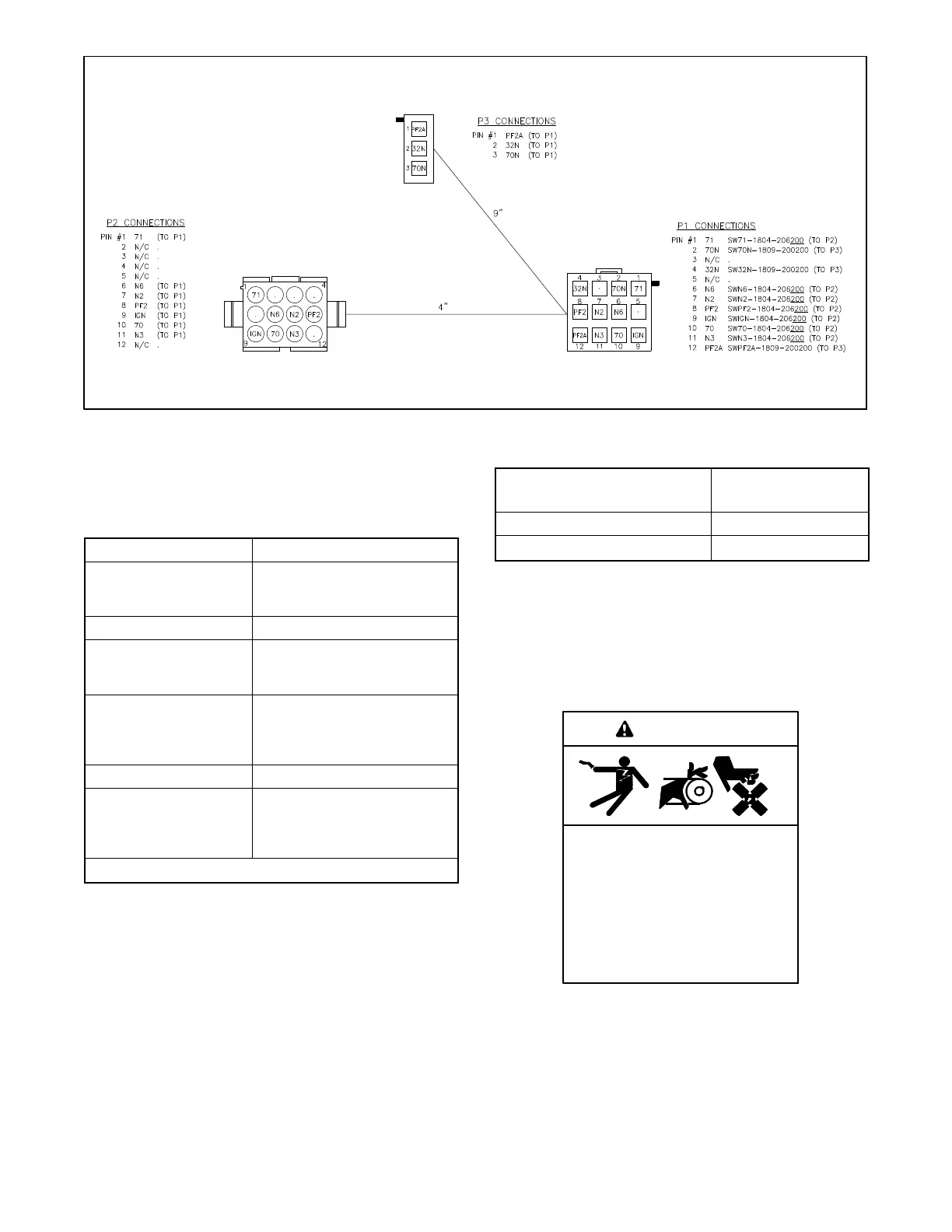
GM52639
TO RELAY BOARD P14
TO ENGINE HARNESS TO CONTROL BOARD P11
Figure 4-12 Relay Board Connection Harness
Check for loose customer connections to terminal strip
TB1 on the relay board. See Figure 4-10 and
Figure 4-13.
TB1 Terminal Label Description
COMMON FAULT NC Common fault relay normally
closed contact.
Opens on a fault.
COMMON FAULT COM Common fault relay common
COMMON FAULT NO Common fault relay normally
open contact.
Closes on a fault.
AUX RUN NC Auxiliary run relay normally
closed contact.
Open when generator set is
running.
AUX RUN COM Auxiliary run relay common
AUX RUN NO Auxiliary run relay normally
open contact.
Closed when generator set is
running.
Note: Use maximum 14 AWG wire for TB1 connections.
Figure 4-13 TB1 Customer Connections
Check the harness and wiring for open circuits or shorts.
Replace the harness or customer wiring as necessary.
Check that the ratings of the customer’s connected
equipment do not exceed the relay contact
specifications shown in Figure 4-14.
Contact Ratings 10 A @ 120 VAC
10 A @ 28 VDC
Maximum Operating Voltage 250 VAC/60 VDC
Maximum Switching Capacity 440 VA/75 W
Figure 4-14 Relay Contact Ratings
An LED is associated with each relay. See Figure 4-10.
The LED indicates power to the corresponding relay. If
the LED is illuminated but the relay is not activated, the
relay is faulty. The individual relays are not replaceable.
If one or more relays are faulty, replace the entire RIB.
Accidental starting.
Can cause severe injury or death.
Disconnect the battery cables before
working on the generator set.
Remove the negative (--) lead first
when disconnecting the battery.
Reconnect the negative (--) lead last
when reconnecting the battery.
WARNING
 Loading...


