TP-7091 4/23 43
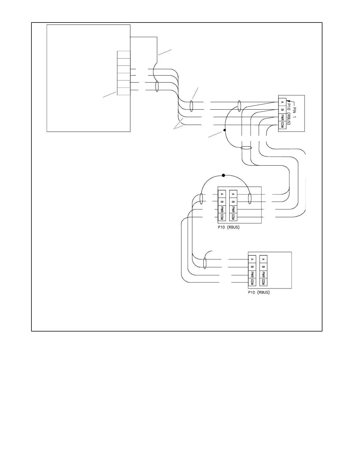
1. Generator set terminal block. Check the decal on the generator set for terminal block connections.
2. Connect one end of each cable shield to GROUND at the generator set.
3. Communication cable.
4. 12 AWG or 14 AWG leads for PWR and COM.
5. Connect shields together as shown.
6. Leave one end of the cable shield disconnected at the last device.
Figure 31 Accessory Module Connections with 12- 14 AWG Power Leads
Communication Cable Specifications
section for
maximum total cable lengths.
RXT transfer switch with standard or combined interface/
load management board. Do not use a load shed kit with
a combined interface board.
Note:
The RXT ATS and/or PIM may be equipped with
an alternate single-row connector for P10. See
Supplement TP-7239 for instructions.

 Loading...