TP-6519 8/17 63Section 5 Component Testing and Adjustment
Governor System Operation Test Procedure
1. Verify that the carburetor throttle linkage is
connected to the stepper motor as shown in
Figure 5-22.
2. Look for broken or loose wiring or plug connections
if the stepper motor moves erratically. C heck the
condition of the throttle linkage, and verify that the
throttle plate closes completely.
3. Check the operation of the stepper motor at
startup.
a. If the throttle moves to the fully open throttle
position and then steps to and remains in the
fully closed position, the engine speed input is
probably missing. The engine starts and then
shuts down on an overspeed fault. Proceed to
step 4 to check the magnetic pickup.
b. If the throttle linkage moves erratically or not at
all at during startup, proceed to step 8 to check
the stepper motor.
4. Stop the generator set and check the resistance of
the magnetic pickup.
a. Stop the generator set. Remove housing
panels as required to gain access to the front of
the engine.
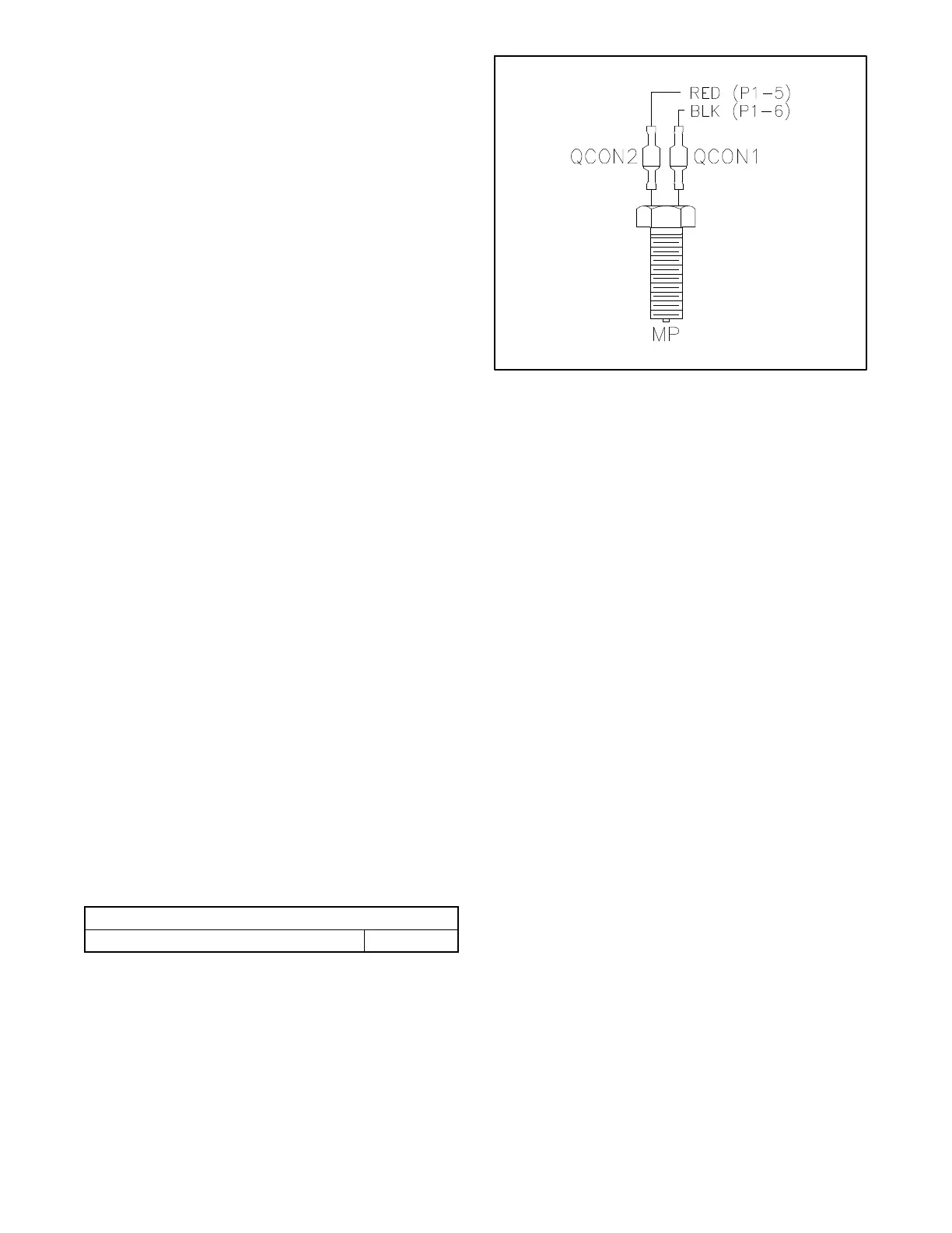
b. Disconnect the magnetic pickup at QCON1
and QCON2. The magnetic pickup must be
isolated from the generator controller to allow
an accurate resistance measurement.
c. Measure the electrical resistance through the
magnetic pickup at QCON1 and QCON2. See
Figure 5-25.
d. Compare the resistance measurement to the
value shown in Figure 5-24. If the resistance is
outside of the specified range, replace the
magnetic pickup.
e. Reconnect QCON1 and QCON2.
Magnetic Pickup Resistance
Resistance across QCON1 and QCON2 1.3 -- 1.9 k
Figure 5-24 Magnetic Pickup Resistance
6519
Figure 5-25 Magnetic Pickup Leads
5. Verify the operation of the magnetic pickup by
connecting a v oltmeter to the magnetic pickup
leads. See Figure 5-25.
If the air gap is correct, the voltage should be
1.75 volts AC minimum during engine cranking.
6. If the voltmeter displays less than 1.75 volts AC,
check the air gap as described in the following
steps before replacing the sensor. Verify that the
magnetic pickup air gap is 0.5 mm (0.020 in.).
Measure the air gap at 3 or 4 places to get an
accurate reading. See Figure 5-26.
a. Stop the generator set. Remove housing
panels as required to gain access to the front of
the engine.
b. Remove the engine blower housing.
c. Use a feeler gauge to check the gap. The gap
should be 0 .5 mm (0.020 in.).
d. Adjust the air gap, if necessary, by loosening
the locknut and turning the pickup. See
Figure 5-26.
e. Hold the pickup in position and retighten the
locknut.
 Loading...


