TP-6519 8/17 75Section 6 Disassembly/Reassembly
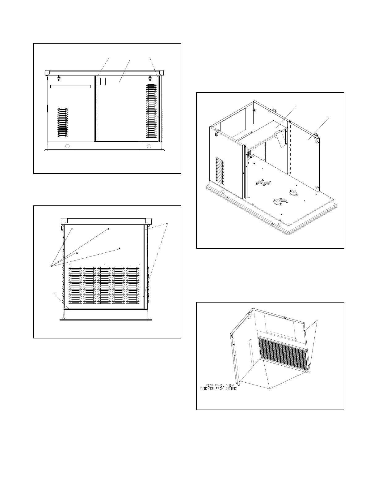
6. Remove two door screws. See Figure 6-3. Lift the
service-side door up and off.
GM51561
2
1. Door screws (2 ea.)
2. Right side door
1 1
Figure 6-3 Right Side Door
7. Remove the front panel. See Figure 6-4.
GM51561
1. Screws, qty. 4 (outside)
2. Screws, qty. 3 (inside)
1
2
2
Figure 6-4 Front Panel Mounting Screw Locations
8. Unplug the carburetor heater (if equipped) from the
120VAC receptacle.
9. Unplug the battery charger from the 120VAC
receptacle.
10. Disconnect the generator set engine starting
battery, negative (-- ) lead first.
11. Disconnect output leads or load circuit cables at
the field-connection terminal block.
12. Remove the heat shield over the silencer by
removing four screws. See Figure 6-5.
13. From the inside of the enclosure, remove the
remaining screws to remove the non-service side
housing panel. See Figure 6-5.
1
GM51561
1. Remove silencer heat shield
2. Left side panel
2
Figure 6-5 Left Side Panel (bulkhead and generator
set not shown)
14. From the inside of the enclosure, remove five
screws to remove the rear (exhaust end) panel.
SeeFigure6-6.
GM51561D
1. Screws,qty.5
1
1
Figure 6-6 Rear Panel Mounting Screw Locations
(viewed from inside the enclosure)
 Loading...


