TP-6519 8/17 77Section 6 Disassembly/Reassembly
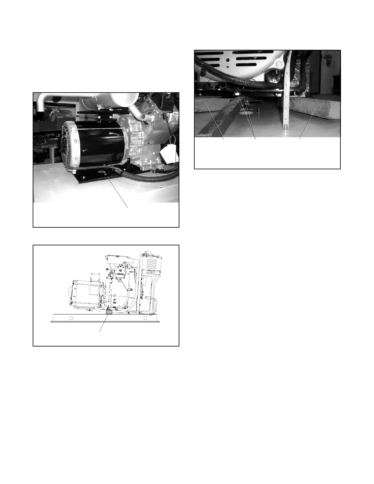
18. If the unit is not equipped with the stiffening plate
shown in Figure 6-10, raise the alternator end of
the generator set enough to place a thin block of
wood beneath the rear of the engine. See
Figure 6-11.
Note: Use a hoist or lifting device that is rated for
the weight of the generator set. See
Section 6.1.
1. Stiffening plate
6519
1
Figure 6-10 Stiffening Plate (if equipped)
GM51561
1
1. Engine support block
Figure 6-11 Generator Set, Right Side
19. If the unit is equipped with a stiffening plate as
shown in Figure 6-10, raise the alternator end
75--90 mm (3--3.5 inches). Place wood blocks
under both sides of the plate. See Figure 6-12.
20. Remove the bolts holding the vibromount and the
stiffening plate to the bottom of the alternator. See
Figure 6-12.
6519
1
1. Bolts
2. Support blocks
2
2
Figure 6-12 Supporting the Alternator
21. Disconnect the alternator harness wiring inside the
controller junction box. See the wiring diagrams in
Section 7.
a. Disconnect brush leads FP and FN and stator
lead 66 from the SCR module.
b. Disconnect lead 55 from fuse F1.
c. Single-phase models: Disconnect leads 11
and 44 at quick connects 5 and 6.
Three-phase models: Disconnect leads V7, V8
and V9 at quick connects 5, 6 and 7.
d. Disconnect leads 2 and 3 from neutral stud L0.
e. Disconnect leads 1 and 4 from the circuit
breaker.
22. Remove 4 screws securing the brush cover to the
alternator end bracket. See Figure 6-13.
23. Disconnect brush leads FP and FN.
 Loading...


