260 Section 14 Load Management TP-6953 7/19
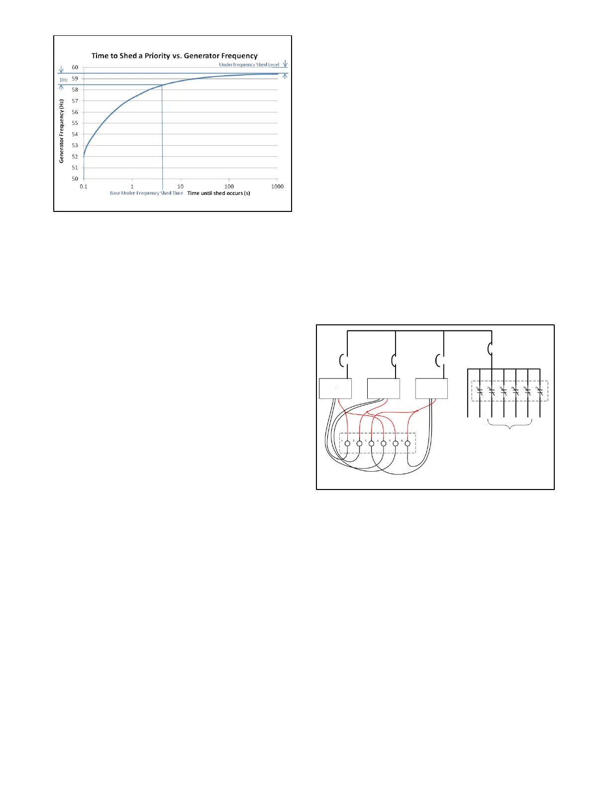
Figure 14 -7 Load Shed Timing Based on Generator
Frequency
(Underfrequency Shed Level = 0.50 Hz,
Base Underfrequency Shed T ime = 5 sec.)
If the generator was overloaded to 11 0% of
capacity and this caused the generator frequency
to dip to 58 Hz, Underfrequency Shed would cause
priority6toshedin2seconds(OverloadShed
would also be active, but would require 5 seconds
to shed, so it would only be 40% shed).
When removing priority 6 decreases the load to
105% and causes the frequency to recover to
58.5 Hz, the curve in Figure 14-7 would indicate
that priority 5 would shed in 5 seconds, but
Underfrequency Shed has acceleration of 0.56,
meaning that each priority sheds in half as much
time as the previous priority if the condition is not
cleared, hence priority 5 would actually shed in
2.5 seconds (Overload Shed would have a total
time of 7.5 seconds, meaning that another 33%
would be added to the 40% shed condition, making
priority 4 73% shed due to overload).
When removing priority 5 decreases the load to
93% and allows the frequency to recover to 59.2 Hz
in the next two seconds, the curve in Figure 14-7
would indicate that the time to shed would be about
60 seconds, but the acceleration drops it to
0.25* 60 = 15 seconds. Even at that load, the
generator is allowed to recover to rated frequency
by the underfrequency shed logic, but the overload
shed logic will still cause the priority 4 to shed in
another 15 seconds (45 sec time to shed at 93%
load, and shed already 67% complete).
14.2.2 Sequence of Operation—
Paralleling System
This sequence follows the operation of a normal
paralleling system which uses Load Management. The
Load Management log ic uses the paralleling bus
frequency and the paralleling bus percentage of rated
capacity to determine a need to add or shed load. A
generator does not have to be running to support Load
Management.
When a start signal is applied to any of the generators in
the paralleling system, all the generators that are in auto
and have no shutdown faults will start and all the load
priorities will shed. T his shed is intended to remove
excess load from the system so that a single generator
can support it.
Figure 14-8 illustrates the system after the first
generator has reached rated voltage and frequency and
has closed to the paralleling bus (any of the generators
can be the first to close, d epending on which generator
reaches rated voltage and frequency first).
25kW
Critical
loads
Most
important
non-
critical
loads
Least
important
non-
critical
loads
Additional
non-critical
loads
Load
Shed
Panel
Load
Shed
Panel
Generator #1
(50kW rating)
18kW 3kW 10kW 12kW 5kW
25kW
8kW
Generator #2
(50kW rating)
Generator #3
(50kW rating)
Figure 14-8 One Generator Energizes the Paralleling
Bus
The load on the first generator to connect to the
paralleling bus is merely that of the critical loads.
The time t o Add Priority 1 can be determined from
Figure 14-9 based on a 50% generator load. The curve
indicates approximately 1500 seconds (25 minutes)
before priority 1 will add.
After synchronizing to the paralleling bus, generators #1
and #3 will close their paralleling breakers, providing a
total of 150 kW of capacity to the paralleling bus. The
25 kW load is only 17% of the capacity of the bus with all
three generators supplying it, hence the time to add a
priority drops to 26 seconds.
When priority 1 adds, the output from generator #1 that
drives the load shed priority will de-energize.
 Loading...

