TP-6953 7/19278 Section 15 Alternator Disassembly/Reassembly
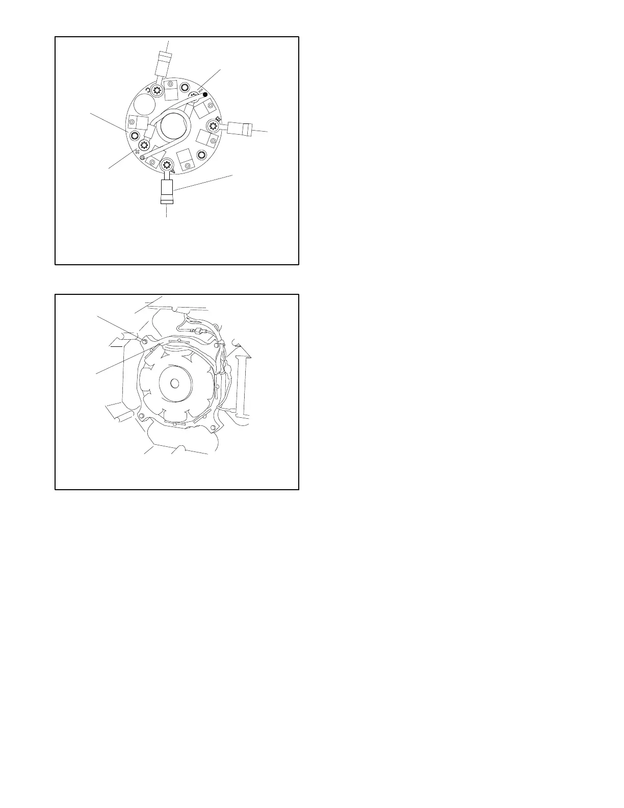
1. Rotor F2 lead to negative (- ) terminal
2. Exciter armature leads (3) AC to A, B, And C terminals
3. Rotor F1 lead to positive (+) terminal
4. Rectifier module screw s, qty. 3
GM89444A-D
4
1
2
3
Figure 15 -15 Rectifier Module Connections
5588614
1
1. Exciter field bolts (4)
2. Exciter field
2
Figure 15 -16 Installing Exciter Field
18. Use tie wraps to secure the wires as necessary.
19. Install the alternator guard and hardware.
20. Reinstall the junction box and/or control box
components and related wiring. Do not install the
panels at this time.
21. Reconnect the leads to the circuit breaker and
neutral stud (LO) a s marked during disassembly.
Note: For voltage reconnection diagrams, refer to
the wiring diagrams in Section 17.
Note: Check the generator set nameplate to verify
the original voltage configuration on the unit.
22. Reconnect all controller-to-engine and engine-to-
alternator harnesses and wiring in the junction box.
23. Reinstall the junction box panels.
24. Reconnect all of the external connections—the
exhaust line, the fuel line to the fuel pump filter inlet,
the remote interface connector, the AC output
leads, and the battery cables to the battery
(negative (- ) lead last).
25. Reconnect the engine starting battery, negative (- )
lead last.
26. Reconnect power to the battery charger and other
AC accessories, if equipped.
 Loading...

